 English
  简体中文
简体中文  한국어
한국어  Deutsch
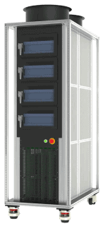
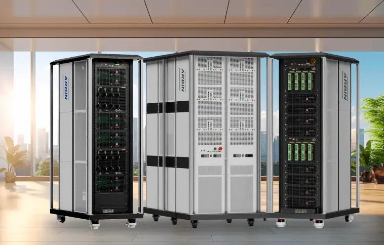
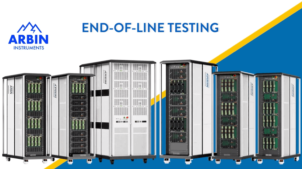


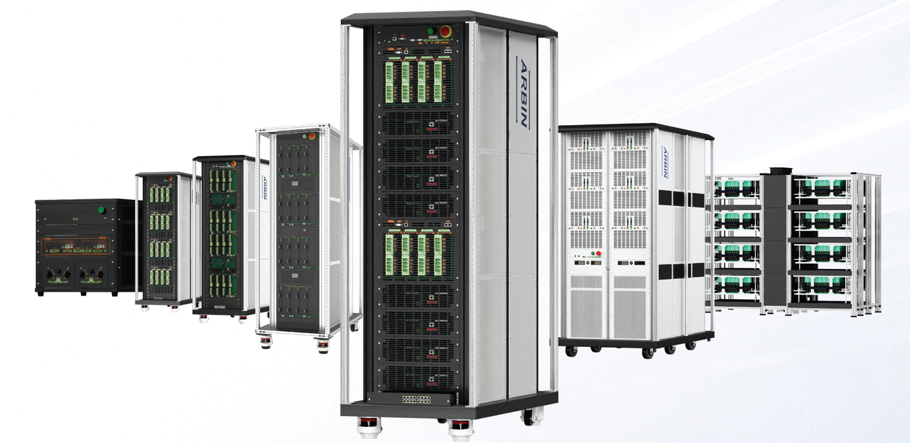
Battery Module & Pack Testing Systems
Battery Module and Pack Testing from 20 V to 1,500 V
Arbin manufactures linear and regenerative testers for battery module and pack testing, from 20 V modules to 1,500 V packs at up to 1.8 MW. Tests are written and run in MITS, which integrates the whole test facility: chamber control, BMS communication over CAN, and results written straight to your database.
Tests built in MITS
30+ programmable control types, 90+ meta variables and 127 reusable sub-schedules, with drive-cycle profiles built in the Simulation Editor.
CAN and BMS communication
CAN 2.0 and CAN-FD with DBC file import, plus UDS and SMBus. BMS signals are logged alongside voltage and current on one timebase.
Open APIs when you need them
ArbinCTI over TCP/IP with Python and C# clients, and ArbinDriver for direct control from a PLC or your own application.
Energy back to your facility
Up to 92% of discharge energy returned to the grid at 0.99 power factor, with anti-islanding disconnection in roughly 40 ms. Air-cooled, no plant water.
Find the Right Module & Pack Testing Platform
Three systems, grouped by technology (linear vs regenerative) and application (module vs pack). All three run MITS, build schedules and drive-cycle profiles the same way, and share the same CAN and API interfaces - moving test programs from module testing to pack testing does not mean relearning the software.
Module Testers
All-Purpose · Linear
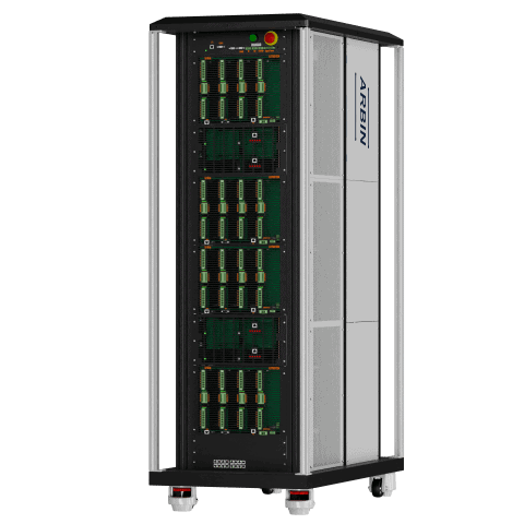
LBTS-Module
20 V–100 V · 0.1 A–80 A · up to 32 ch
Arbin's linear module tester, built for module R&D and end-of-line work. Four auto-switching current ranges per channel, up to 960 A with channels paralleled, in a compact air-cooled chassis that runs on a standard three-phase supply.
Regenerative
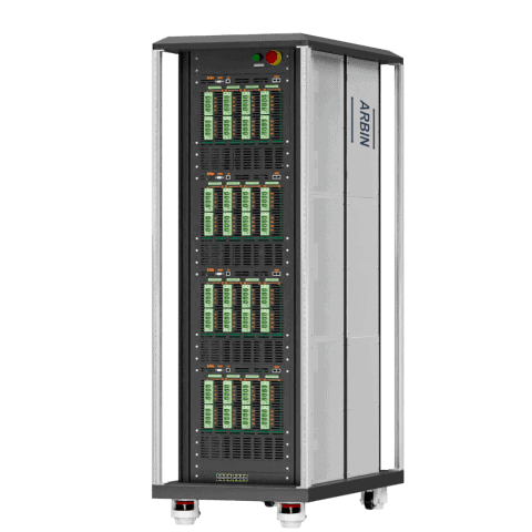
RBT-Module
30 V–200 V · 10 A–300 A/ch · to 1,800 A
High-current module cycling with true bipolar circuitry and no switching time across zero, so a drive cycle is followed rather than approximated. Up to 96 kW charge power per module, with up to 90% of the discharge returned to the grid
Pack Testers
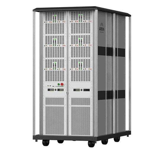
Regenerative · High Voltage
RBT-Pack
300 V–1,500 V · 50 A–200 A/ch · to 360 kW/chassis
Pack-level cycling, end-of-line and BMS validation at full pack voltage. Dual auto-selecting voltage ranges per channel, Gen3 SiC power stages returning up to 92% of the discharge, and the standard drive cycles running natively.
Testing cells rather than modules?
The cell range runs from 10 µA on a benchtop unit to 1,600 A paralleled, including per-cell thermal control and high-throughput incoming QC.
Which module or pack platform fits your work?
The comparison table below has the full numbers. This is the reasoning behind which system suits which job, and what the software and the facility need to provide alongside it.
Not sure which applies? Send the module or pack voltage window, peak current and power, and the channel count you need. An application engineer will come back with a specific configuration and what it asks of the room.
Integration interfaces
What the system connects to alongside MITS, and how it opens up when a rig has to be driven from outside.
Test the pack against real load profiles
Module and pack testing is run against load profiles rather than constant currents. Profiles are built in the MITS Simulation Editor and called from a schedule like any other step, or driven over CAN while the test runs. The same channels also emulate a battery, so a charger, inverter or BMS can be tested closed-loop before a real pack exists.
Control is built from 30+ programmable control types, 90+ meta variables, 16 user-defined variables, up to 9 nested loops and 127 reusable sub-schedules, with nested AND/OR termination logic — so a validated drive-cycle procedure is called rather than rebuilt. MITS runs on Windows, macOS and Linux from one codebase, and MITS 11, 10 and 8 remain supported.
Side by Side
Compare Arbin Module & Pack Testing Systems
Compare each platform by application, voltage window, channel count, and how it integrates into a wider test system. Current and power figures are per channel; combined series and parallel ceilings are given on their own line and never folded into the headline range.
| Product | Best For | Voltage & Current | Channels | Integration & Control |
|---|---|---|---|---|
| Module Testers | ||||
| LBTS-Module All-Purpose Linear module cycler View Product → | Module R&D and end-of-line testing where channel count matters more than power, and the tester sits on a production line rather than a grid connection. | 20 V – 100 V Six range options. 0.1 A – 80 A per channel across four auto-switching ranges; up to 960 A paralleled. Rise time under 1 ms. | 4 – 32 4 or 8 per module, up to 32 per chassis | MITS platform, shared Third-party chamber and automation-software integration, real-world profile simulation, and data into MS SQL, PostgreSQL or Kafka. |
| RBT-Module Regenerative High-current regenerative module cycler View Product → | High-current module cycling, drive-cycle simulation and BMS-in-the-loop work, and long-running tests where facility power and cooling are a live constraint. | 30 V – 200 V Five range options, all operating down to 8 V. 10 A – 300 A per channel across up to three auto-switching ranges; 1,800 A paralleled per chassis. 24–96 kW charge power per module. | 2 – 24 2, 4 or 8 per module; up to 3 modules per chassis | Full stack CAN 2.0/CAN-FD with DBC import, SMBus, UDS; ArbinCTI and ArbinDriver; analog and digital I/O; MTCI chamber and chiller control; auxiliary voltage, temperature and pressure. Regenerates up to 90%. |
| Pack Testers | ||||
| RBT-Pack Regenerative High-voltage regenerative pack cycler View Product → | Pack-level lifecycle and end-of-line testing, BMS validation, and the standard drive cycles — FUDS, HPPC, DST, WLTP — at full pack voltage and power. | 300 V – 1,500 V Two auto-selecting ranges per channel; charge from 0 V, discharge floor 20 V to 60 V by range. 50 A – 200 A and 60–200 kW per channel; 180–360 kW per chassis. Combined: 1,500 V, 3,000 A, 1.8 MW. | 2 – 6 Per chassis, voltage dependent; chassis parallel for more | Full stack Same interfaces as RBT-Module — CAN 2.0/CAN-FD with DBC import, SMBus, UDS, ArbinCTI, ArbinDriver, I/O and MTCI — plus Rint-model battery simulation for HIL. Regenerates up to 92%, anti-islanding in ~40 ms. |
Product-family ranges are summarized for comparison. Available voltage, current, channel-count and power combinations depend on the selected configuration, and chassis output power is customizable in increments. Testing cells rather than modules? See LBTS-Cell, RBT-Cell, HPS and the rest of the cell range.
Regenerative Battery Testing Systems
Configure Your RBT System
Start by selecting the system type, then configure it step by step. Both series use regenerative circuitry that returns discharge energy to the facility grid.
Configure Your RBT-Module
Choose a channel module, voltage range, and chassis density. The system specification updates as you select.
1 Channel module
2 Voltage range
All ranges support 8 V minimum operation. Discharge to 0 V available upon request.
3 Modules per chassis
4 AC/DC power supplies per module
Each supply adds +12 kW charge and -11 kW discharge power. Available supply counts depend on the voltage range and chassis density.
Part number: · Reference configuration:
* Charge and discharge power are calculated from the number of AC/DC supplies selected, at +12 kW charge and -11 kW discharge per supply. Parallel current assumes all channels in the chassis are paralleled, up to the 1,800 A chassis limit. Contact Arbin to confirm the final power allocation for a specific configuration.
| Module | Modules / Chassis | Channels / Chassis | Current Ranges (±) | AC/DC Supplies per Module | Charge Power per Module | Discharge Power per Module |
|---|
Each AC/DC bidirectional power supply provides up to +12 kW charge and -11 kW discharge power. The maximum supply count, and therefore the maximum power per module, also depends on the voltage range selected; use the configurator above for the available combinations.
Configure Your RBT-Pack
Choose a model, facility AC input power, voltage range, channel count, and total output power. The system specification updates as you select. Channels can be paralleled to increase current and power output, and RBT43012 and RBT44012 channels can also be configured in series to increase voltage.
1 Model
2 AC input power
Every system requires 2 facility power connections: the selected three-phase feed plus a 200 to 240 VAC single-phase feed. The input power also sets the top voltage range on RBT44012 (700 V or 750 V) and RBT46012 (1,400 V or 1,500 V).
3 Voltage range
4 Channels
Each channel is served by its own channel module.
5 Total output power
Shared power is one pool distributed across all channels; each channel can draw up to its per-channel maximum, and the pool limits the combined output. Dedicated power reserves the per-channel maximum for every channel simultaneously.
6 Chassis in parallel
Identical chassis can operate in parallel to reach up to 3,000 A and 1.8 MW combined. Paralleled chassis must share the same voltage range and power type, and each chassis requires its own three-phase and single-phase feed.
Part number: · Reference configuration:
* Calculated as total output power divided by the combined current of all channels in parallel. Above this voltage, output current is limited by the total output power rather than the channel current rating. Contact Arbin to confirm the final configuration.
Discharge to 0 V and limited negative voltage operation are supported with appropriate multi-channel configurations and control modes. Systems can be combined to reach up to 1,500 V, 3,000 A, and 1.8 MW.
| Model | Voltage Ranges | Current Ranges per Channel | Channels | Max Power per Channel | Total Output Power | AC Input |
|---|
The complete test cell, not just the cycler
At module and pack scale the cycler is the smallest part of the decision. How the pack is connected, how the heat leaves the room, what the BMS is told, what commands the test, and what the building can supply all shape the result as much as the channel driving it. Arbin specifies all six layers together against your pack and test plan, rather than shipping a chassis and leaving the rest to the installation.
Every layer is specified against your pack and your test system, not sold as a bundle. Send us what you are testing and how you intend to drive it, and an application engineer will come back with a configuration matched to both.
Contact UsTell us what you are testing
Most configurations are settled in a single conversation, because the four things below narrow the options far faster than a catalogue does. Send them across and a sales engineer will come back with the system that fits, the interfaces it needs, and what it asks of your facility.
