 English
  简体中文
简体中文  한국어
한국어 
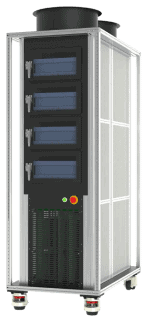
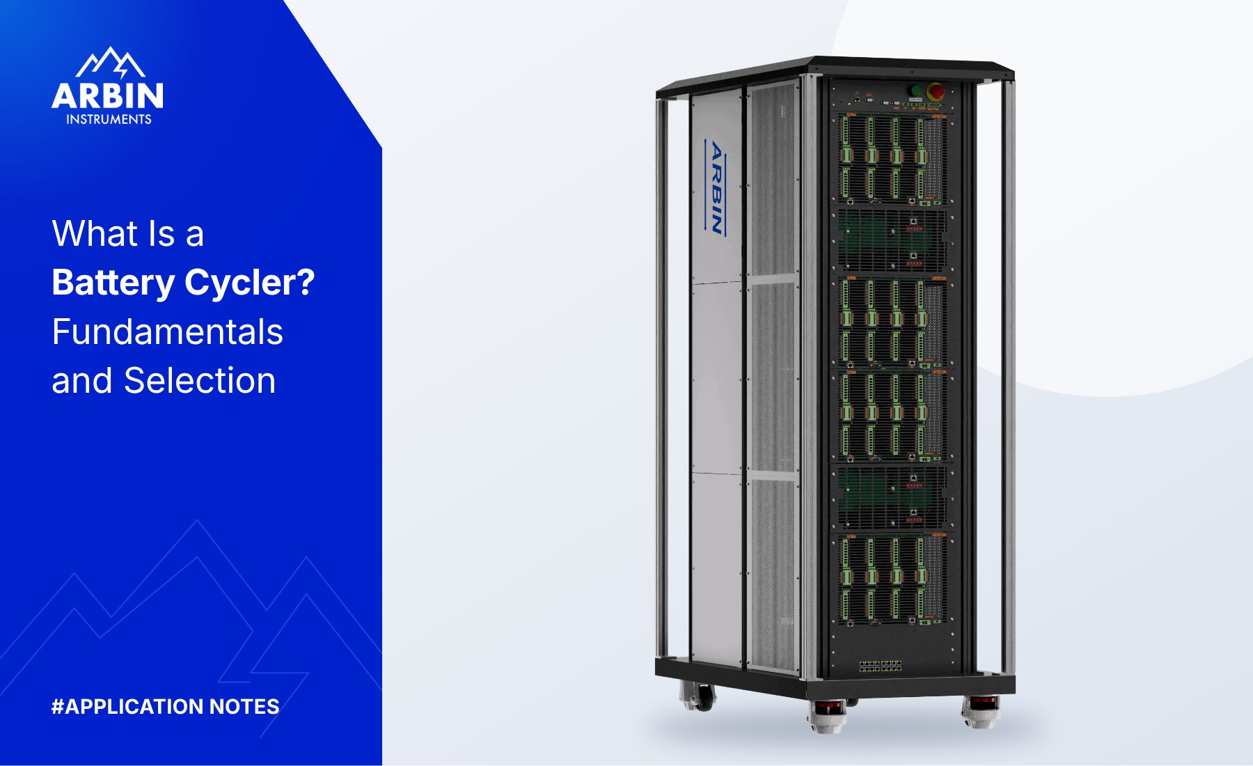





Regenerative Battery Testing System
RBT-Module Series
High-power, fully digital battery pack testing from 30 V to 200 V — built on Gen3 SiC regenerative circuitry that returns up to 90% of discharge energy to your facility, with ±0.02% FSR accuracy and true bipolar switching for seamless charge–discharge transitions.
30 V - 200 V
Voltage range across the series
Up to 96 kW
Power per module
Up to 1,200A
300A per channel, parallel channel operation
±0.02% FSR
Voltage & current accuracy
Accuracy you can audit
Accuracy and precision are published as two separate numbers, never blended into one, so you can verify the spec yourself instead of taking a vendor's word for it.
Independently verified
Designed and manufactured under an ISO 9001:2015-certified quality system, supported by an ISO/IEC 17025-accredited testing and calibration laboratory.
35 years of instrumentation
Founded 1991. Arbin reinvests 30% of profits into R&D, funding the precision architecture provided with every Arbin test station.
Built for any lab
Scalable channel density in a compact, air-cooled footprint, with open Python and C# API for the automation you already run.
Highlights of the RBT-Module Series
Four hardware decisions that separate the RBT-Module from a conventional high-power cycler.
Regenerative Energy Recovery
up to 90% returned to the grid
Cut the energy cost of pack cycling
SiC-based regenerative circuitry returns discharge energy to the facility grid: up to 90% on the 100 V and 200 V configurations, up to 82% on 30 V through 60 V. Channels share a common DC link, so a discharging channel's energy is reused by a charging channel before anything draws from the mains.
Net facility power draw, and the cooling load needed to remove waste heat, both fall with it.
Parallel Channel Scaling
any number of channels
Raise the current ceiling without a second chassis
Any combination of sequential channels can be connected in parallel to raise the current handling capability for a single test article, rather than choosing from a fixed set of pre-wired banks. Paralleled operation reaches up to 1,200 A per chassis.
Test a higher-current pack with the channels already installed, instead of adding a second system.
Multiple Current Ranges
auto-selecting, every channel
Full accuracy at lower currents
Each channel module is configured with up to three current ranges per channel. The active range switches automatically during a test, including through constant-voltage control, and the rated accuracy and precision follow it.
Low-current diagnostics and full-power cycling run on the same channel, without moving the pack to another system.
Built-In Safety Features
safety monitoring for every channel
Engineered for high-voltage packs
Precharge circuitry matches the DC bus to pack voltage under digital control before the main contactor closes, preventing inrush. Anti-islanding disconnects the regenerative stage within roughly 40 ms if line voltage or frequency leaves its limits.
A channel-level interlock responds in about 20 µs, backed by integrated breakers, fuses, and isolation contactor relays.
Applications and Test Methods
Each channel operates as an independent, digitally controlled charge/discharge source, so one chassis covers module and pack characterization, life-cycle testing, and incoming QC at up to 300 A and 200 V per channel.

Module and small pack life cycle testing
Cycle modules and packs at up to 300 A per channel across a 30 V to 200 V range, with channels paralleled to raise the current ceiling for a single test article. Time-vs-current, time-vs-power, and Rint-model battery simulation profiles run on the same channel.

End-of-line and incoming QC
Capacity, resistance, and voltage verification on incoming or finished packs. Precharge circuitry matches the DC bus to pack voltage before the contactor closes, and every channel enforces its own safety limits.

Drive cycles and BMS validation
Run FUDS, HPPC, DST, and WLTP profiles with set points down to 10 ms, uploaded or streamed over CAN. Rint-model battery simulation supports closed-loop HIL work and BMS validation.

Automated and adaptive testing
Drive the tester from your own software. ArbinCTI over TCP/IP plus Lua scripting support BMS emulation, digital twins, and adaptive fast-charge strategies.
Supported Test Methods
DRIVE-CYCLE & PROFILE SIMULATION
- FUDS (Federal Urban Driving Schedule)
- HPPC (Hybrid Pulse Power Characterization)
- DST (Dynamic Stress Test)
- WLTP and custom drive-cycle files
- Time vs. Current / Power / Load profiles
Cycling and lifetime
- Battery life cycle testing
- Battery Simulation (Rint model-based)
- Closed-loop HIL testing of external devices
- Dynamic fast-charging optimization
Production and Validation
- Incoming quality control
- Battery Pack End-of-Line (EOL)
- BMS validation over CAN 2.0 / CAN-FD
- Battery Pack R&D
Voltage, Current, and Power Configurations
One measurement specification, one software platform, across the full current span Arbin builds for module and pack testing — up to 1,200 A high-current cycling.
1 Channel module
2 Voltage range
All ranges support 8 V minimum operation. Discharge to 0 V available upon request.
3 Modules per chassis
* Chassis charge power is calculated from the AC/DC supplies installed, at +12 kW charge and -11 kW discharge per supply. Contact Arbin to confirm the final power allocation for a specific configuration.
| Module | Modules / Chassis | Channels / Chassis | Current Ranges (±) | AC/DC Supplies per Module | Charge Power per Module | Discharge Power per Module |
|---|
Each AC/DC bidirectional power supply provides up to +12 kW charge and -11 kW discharge power.
Comparing systems?
Four hardware parameters decide whether test data is suitable to draw a conclusion from. Here is where the RBT-Module lands on each, and the question worth putting to every vendor on your shortlist.
Software and Safety
The two questions a lab asks after the specifications check out: can my team actually drive it, and what happens when a cell misbehaves.
MITS Software
MITS scales from basic charge–discharge cycling to complex protocols with nested conditions. Most tests can be built through the menu-driven interface, while Lua scripting and ArbinCTI are available for advanced automation and external control
- ✓ 30+ programmable control types, 90+ meta variables, and up to 9 nested loops
- ✓Up to 127 reusable sub-schedules, so a validated procedure gets called rather than rebuilt
- ✓Adaptive logging raises acquisition rate during transients and state transitions
- ✓DataWatcher queries the SQL database directly — filter by channel, barcode, or cycle count, overlay up to 9 plots
- ✓PostgreSQL, Microsoft SQL Server, and Apache Kafka streaming
- ✓ArbinCTI TCP/IP API plus Lua scripting for BMS emulation and adaptive control

Safety Architecture
Protection is distributed across channel hardware, an independent controller, and step-level software limits. Critical safeguards remain active independently of the test sequence.
-
- ✓Hardware E-Stop with all-pole disconnection, plus a 2-pin dry-contact trip circuit
- ✓Channel-level safety interlock (~20us) independently disables a faulted channel
- ✓Built-in circuit breakers, protective fuses, and software current/power clamps on every channel.
- ✓Test Object profiles auto-set thresholds from the cell spec and block a test on reverse polarity
- ✓Anti-islanding protection disconnects the regenerative stage within ~40 ms of abnormal grid conditions.
- ✓Behavioral checks flag abnormal rates, voltage excursions, and capacity anomalies
- ✓Tri-color light tower, audible alarms, thermoswitches, variable-speed ventilation


Auxiliaries and Optional Accessories Available to Enhance Testing

Thermal and Environmental
- Seamlessly communicate and control third-party temperature chambers in real-time
- Synchronized multi-channel test logic; temperature-driven step control and automated standby modes
- Chamber temperature and humidity logged alongside electrical measurements for complete test traceability
CAN & SMBus / BMS Integration
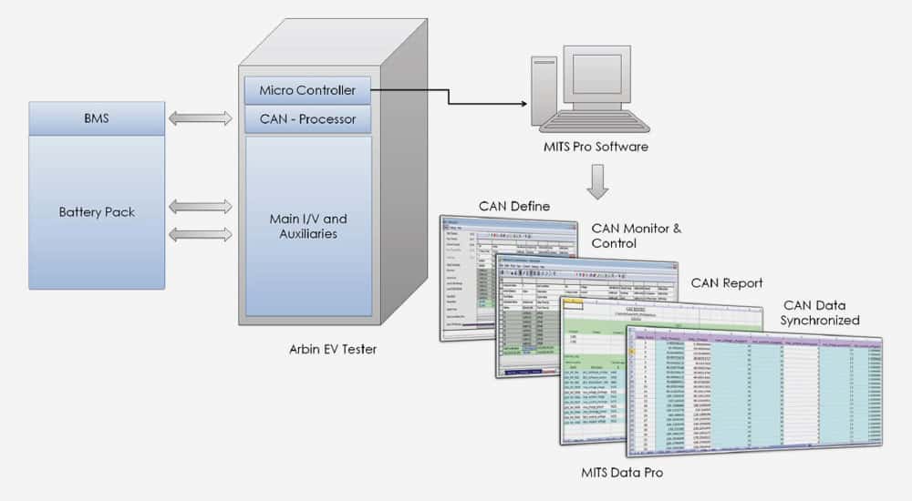
- CAN 2.0 / CAN-FD support — communicate with battery management systems and third-party controllers over standard or flexible-data-rate CAN networks
- Custom CAN message transmission — send scheduled or triggered frames to simulate BMS commands or vehicle network traffic
- Real-time BMS signal logging — capture and timestamp CAN/BMS signals alongside voltage, current, and temperature in a single synchronized dataset
- SMBus 2.0 / I2C support — read and write smart battery registers directly from the test schedule
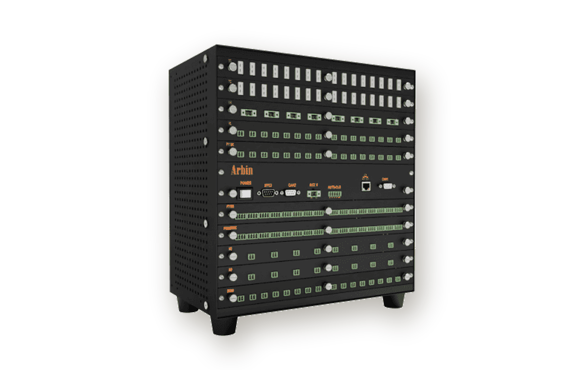
Auxiliaries
- Temperature sensing — real-time thermal monitoring for chambers and cell surfaces
- Auxiliary voltage inputs — monitor individual cell voltages or reference electrodes within packs
- Analog & Digital I/O — control external devices like pumps, fans, valves, and safety interlocks
- Uninterruptible Power Supply (UPS) — detect power loss and safely pause or resume tests

CTI & External Controls
- Custom Test Instructions (CTI) — script test logic beyond standard commands, written in C#/.NET
- Application Programming Interface (API) — connect MITS Pro to LIMS, MES, or in-house systems for automated data exchange
- External device control — drive third-party power supplies, DAQs, or lab instruments directly from the test schedule
- Custom hardware drivers — integrate vendor-specific communication protocols not natively supported out of the box
Tell us what you're testing
Share your voltage and current requirements, channel count, and test objectives. An Arbin sales engineer will recommend the appropriate system configuration and supporting options.
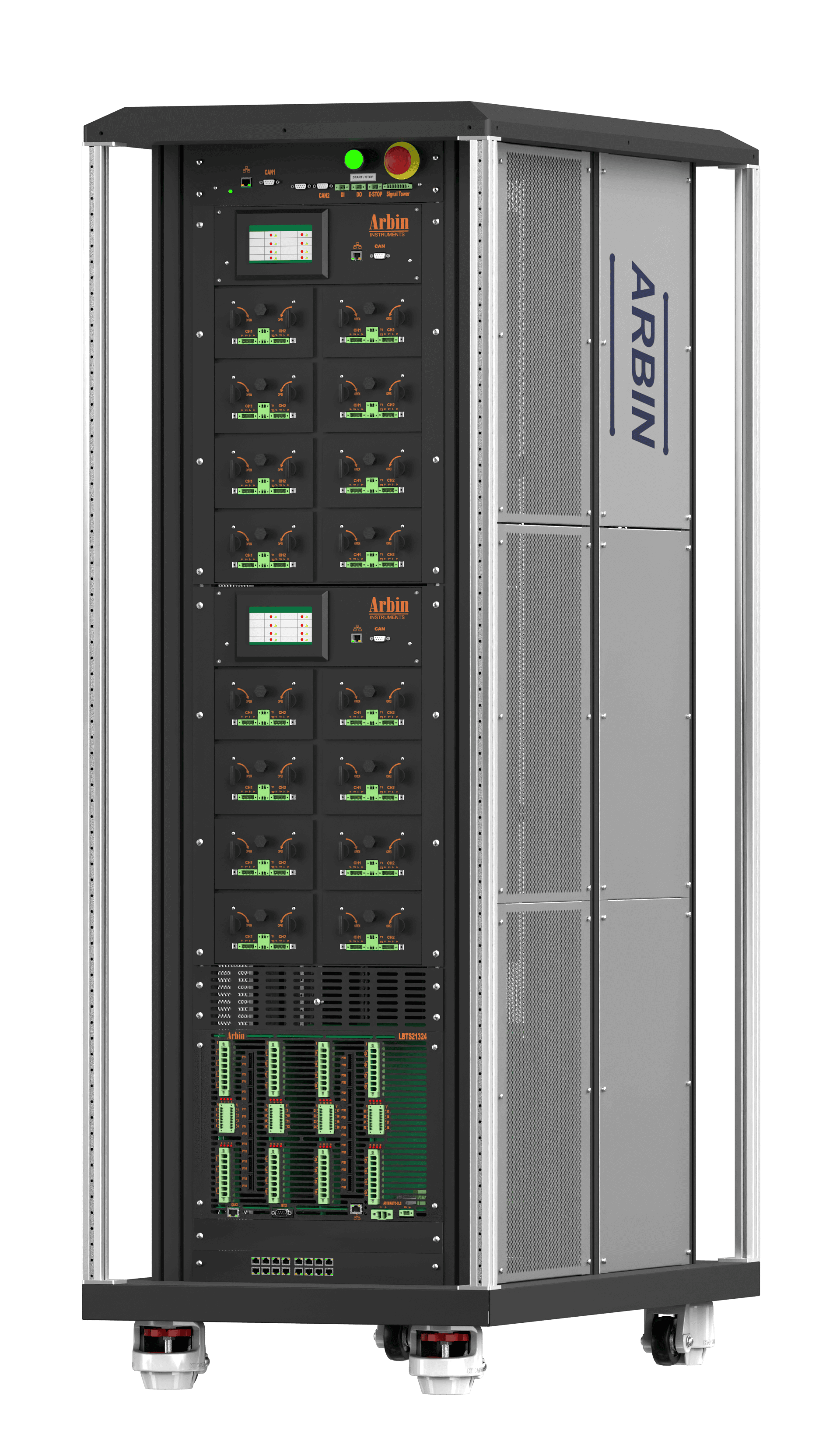
LBTS-MZTC
Turn-key high-precision cell testing solution integrated with Arbin’s patented Cell-Isolating Thermal Chamber
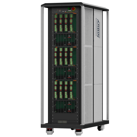
LBTS-Cell High Volume
The perfect solution for high-volume testing. Ideal for incoming quality control and large-scale testing.
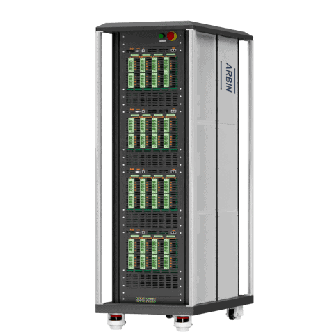
RBT-Cell
Efficient regenerative battery cell testers from 100 A to 1,600 A, with 100ppm precision, built-in safety, and flexible channel paralleling.
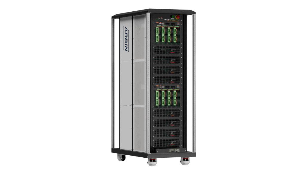
RBT-Module Series
Efficient regenerative battery module testers, 10 A to 600 A up to 200 V, with 0.02% accuracy, built-in safety, and flexible paralleling.
