


I. Purpose and Applicability
Battery testing—whether for electric vehicles, consumer electronics, or industrial systems—demands strict safety protocols. One often overlooked but critical element in test chamber safety is the door switch interlock system. This simple yet powerful mechanism helps prevent injuries, equipment damage, and test data corruption.
In this article, we’ll explore how door switch interlocks work and why they are essential for creating safer battery testing environments.
The Risks in Battery Testing
Battery testing involves exposure to high currents, high voltages, and extreme thermal conditions. Without proper safety measures, technicians face serious hazards, including:
-
Electric shock
-
Thermal runaway
-
Fire or chemical exposure
-
Arc flash during contact or short circuits
To mitigate these risks, test chambers are equipped with safety interlock systems—mechanisms designed to automatically stop or prevent testing whenever the chamber door is opened.
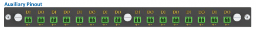
II. Overview about Arbin DIDO Auxiliary system
DIDO stands for Digital Input / Digital Output and is one of Arbin’s key auxiliary systems, designed to work alongside the main charging and discharging system. Its primary function is to facilitate communication and control between the main system and external devices through digital signals.
-
Digital Output (DO): Sends a logical signal (either 0 or 1) to an external device.
-
Digital Input (DI): Receives a logical signal (either 0 or 1) from an external device.
Although the signals are described as logic states, they are in fact voltage signals. This application note focuses specifically on Digital Inputs (DI).
For DI operation:
-
Logic High Voltage: > 3.5V
-
Logic Low Voltage: < 1.5V
-
Input Voltage Range: 0 to 5.5V
For additional specifications, please contact Arbin.
Despite its simplicity, Arbin’s Auxiliary Digital I/O Modules significantly expand the control and automation capabilities of battery testing systems. They enable real-time interaction with external devices such as flow controllers, pumps, relays, alarms, valves, and safety interlock systems.
Through Arbin’s MITS software, all analog and digital I/O channels are fully configurable. Users can define safety conditions, trigger specific test steps, or automate auxiliary processes as part of their battery test protocols. Together, these modules provide the foundation for comprehensive environmental and system-level integration in advanced test setups.
III. Hardware and Software implementation (MITS8 & MITS11)
1. Connection diagram:
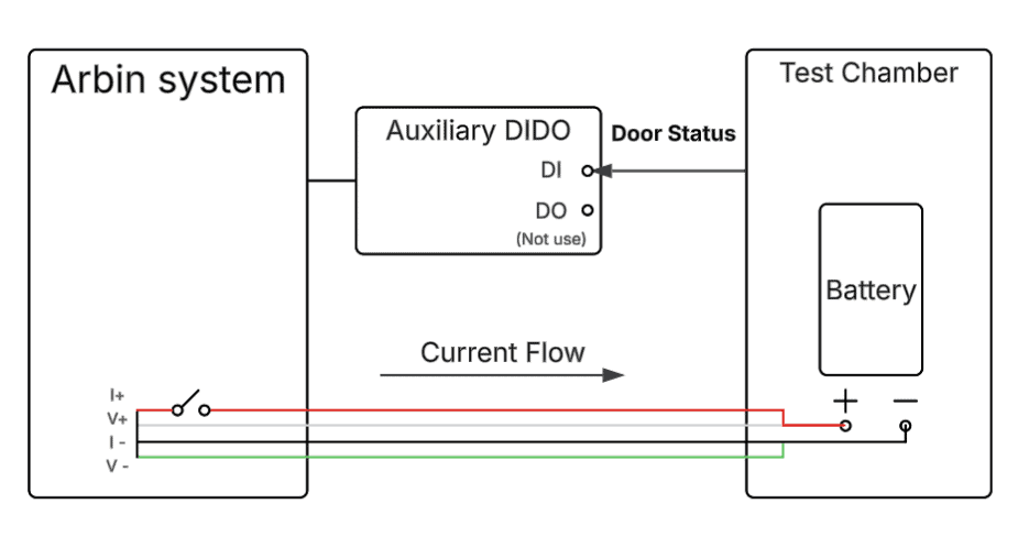
The figure above illustrates the hardware setup. The battery is connected to the IV channel and placed inside the test chamber. The door switch is connected to the DI (Digital Input) port of the Auxiliary DIDO module, which communicates with the main Arbin system. The door switch status is continuously monitored, transmitting its signal to the Arbin system for real-time safety control.
2. Workflow (Safety Interlock with DI/DO)
Door Closed: Safe Operation
-
The door switch outputs a Logic LOW (0) voltage.
-
The DI channel reads LOW, confirming that the door is closed.
-
The system proceeds with normal operation, following the scheduled test sequence step by step.
Door Open: Test Must Stop
-
The door switch outputs a Logic HIGH (1) voltage.
-
The DI channel reads HIGH, triggering an immediate system response:
-
The test stops automatically, and the charging circuit breaker opens.
-
An alarm may be activated (depending on user configuration).
-
3. Software configuration
Proper configuration in MITS8 or MITS11 ensures that the door switch interlock functions as intended. Follow these steps:
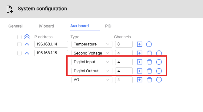
a. Enable Digital I/O Channels
-
Open the System Configuration File in MITS.
-
Confirm that Digital Input (DI) channels are enabled.
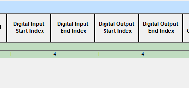
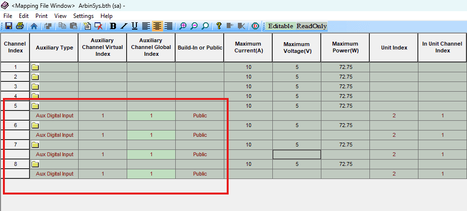
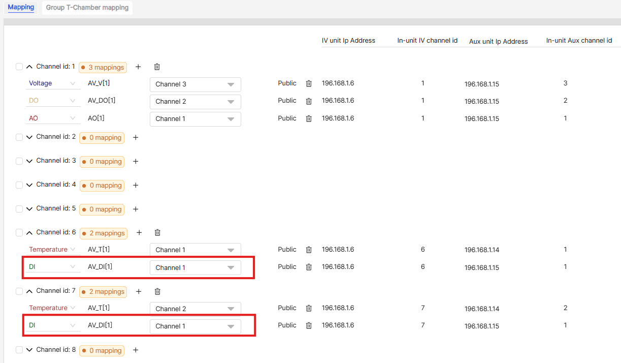
b. Mapping DI to main channels
In the Mapping File, ensure that one or more digital channels are correctly mapped to the main IV channel being used.
Example:
If the tested battery is connected to IV Channel 5, and the chamber’s door lock is connected to Aux Digital Input Channel 1, then you must map Aux Digital Input Channel 1 → IV Channel 5.
Below are some image of mapping file in MITS 8 and MITS 11:
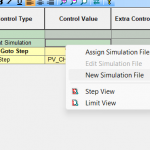
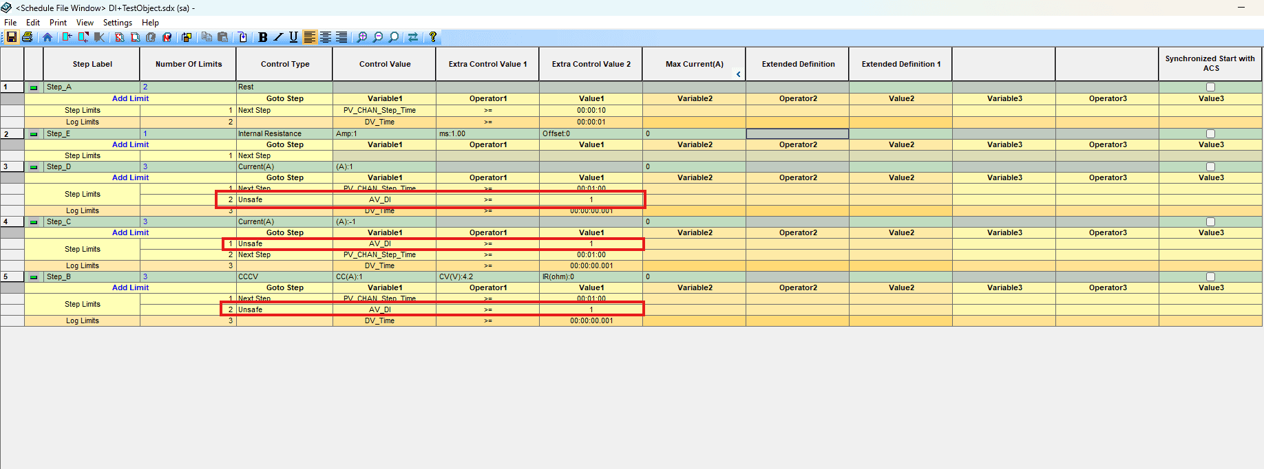
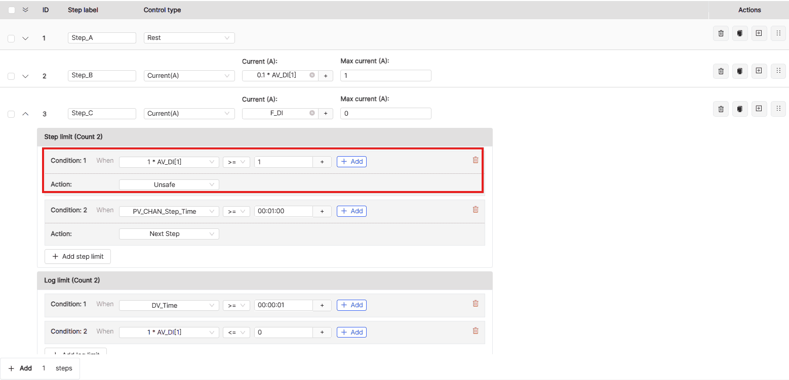
c. Inlcude the safety condition in the schedule
Set the Digital input value check in step limit of steps where door closing is required.
AV_DI >= 1 then jump to Unsafe state, as follows:
During charge or discharge operation, the door sensor continuously monitors for unsafe conditions.
-
If the sensor detects a value above the threshold level, it generates a Logic HIGH signal (1).
-
This signal is sent to the Digital Input (DI) channel, which immediately triggers a Step Jump to the designated “Unsafe” step in the test schedule.
-
At this point:
-
The alarm is activated.
-
The channel is flagged with “Unsafe Status” in the Monitor and Control Interface, alerting the operator to take action.
-
This mechanism ensures that testing halts promptly in unsafe conditions, protecting both equipment and personnel.
Final Thoughts
A door switch interlock may seem minor—but in battery testing, it’s a critical safety component. Whether you’re running a small lab or a full-scale EV battery test rig, installing a simple door switch can protect your team, your equipment, and your results.
*References:
Safety Features for Battery Test Chambers
Battery Test Methods/Specifications and Battery Test Chamber

