


Introduction
The Arbin Auxiliary Voltage Input Module enables precise, high-resolution voltage monitoring for battery testing applications that require measurements beyond the standard I/V channels. Typical use cases include monitoring individual cell or module voltages within a larger pack, measuring reference electrodes in three-electrode cells, or comparing BMS data with directly measured values.
Each module supports 8 independent channels with a ±5 V input range, ultra-high input impedance (100 GΩ), and 24-bit resolution. Measurement accuracy is ±0.05% of full-scale range. Additional voltage ranges (±10 V, ±25 V, ±50 V, ±100 V) are available upon request.
The module features high common-mode isolation on all input channels, allowing signals to float independently or be referenced to different grounds. This design enables safe operation in stacked cell configurations, floating reference setups, or systems where inputs need to be connected in series for differential voltage monitoring. Each channel is electrically isolated and can safely accommodate signals with up to 500 V of common-mode voltage.
All auxiliary voltage data is logged synchronously with the main I/V channels in Arbin’s MITS software and can be used for safety thresholds, test control, and dynamic step transitions. Channels can be flexibly mapped in one-to-one, one-to-many, or many-to-one configurations relative to the main charge/discharge channels.
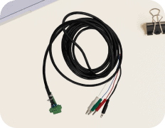
Compatible cable options include bare wire, banana plug, or alligator clips. The module connects via standard Phoenix 2-pin connectors and integrates easily with new or legacy Arbin systems via plug-and-play auxiliary enclosures.
Reference Electrodes
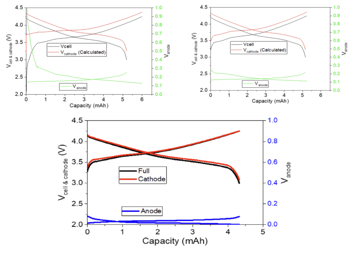
When researching battery materials, the use of a reference electrode (RE) allows researchers to measure and differentiate the contribution of each component of the cell to its overall performance. Three-electrode experiments help identify which electrode (anode or cathode) limits the cell performance during long-term testing. It is important to identify how each electrode is contributing to cell degradation under various test conditions instead of blindly experimenting with one or both.
Cell/Module Voltages
Battery packs and modules no matter the size are comprised of multiple cells and in the case of packs, modules. The number of cells or modules and their series/parallel configuration can vary widely, but the need to monitor these smaller component voltages is always relevant. It is important for the voltage of multiple cells/modules to remain uniform with one another or else they may fail if becoming unbalanced (non-uniform voltage). Most battery packs and modules will contain a battery management system (BMS) that keeps the modules and cells balanced with each other.
Available Options
- −5 V to 5 V
- −10 V to 10 V
- −25 V to 25 V
- −50 V to 50 V
- −100 V to 100 V
The quantity of auxiliary voltage inputs are offered in multiples of 8, and Arbin can provide 8~512 inputs. Please discuss with an Arbin sales engineer if more than 512 inputs are needed.
Mapping Flexibility
Arbin’s auxiliary voltage inputs may be flexibly mapped by the user with the main I/V charge-discharge channels. They can be assigned as 1:1, 1:many, many:1 and anything in-between.
Specifications
| Name | Specification | ||||
| Number of Inputs | 8 | ||||
| Channel Type | ±5 V | ±10 V | ±25 V | ±50 V | ±10 V |
| Input Range | −5 V to 5 V | −5 V to 5 V | −5 V to 5 V | −5 V to 5 V | −5 V to 5 V |
| Input Impedance | 100 GΩ | ||||
| Measurement Accuracy | ±0.05% FSR | ||||
| Measurement Resolution | 24-bit | ||||
| Sampling Speed | 45 ms | ||||
| Common Mode Voltage Range | Up to 500 V | ||||
| Channel Isolation | Electrically isolated inputs (high common mode) | ||||
| Series Connection Support | Inputs may be connected in series | ||||
Note: Auxiliary data is logged at the same rate as main I/V channel data and synchronized with the main I/V channel data based on test schedule setting.
Hardware Illustrations
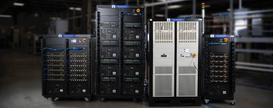
The “auxV” modules can be added to any Arbin testing system, but there may be an age limit for some older models. Arbin will provide a small auxiliary box (of various sizes) containing the inputs that is plug and play with built-in networking to the existing Arbin system.
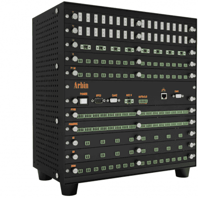
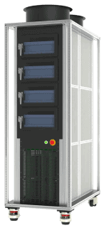
Figure 1: Arbin Auxiliary Chassis
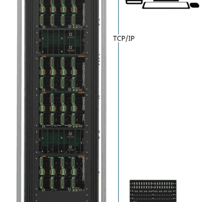
Figure 2: Example TCP/IP Connection to Arbin Main System
Auxiliary Module Illustration
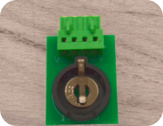
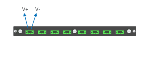
Each board of auxiliary voltage inputs will provide (8) 2-pin connectors for +/- voltage reading.
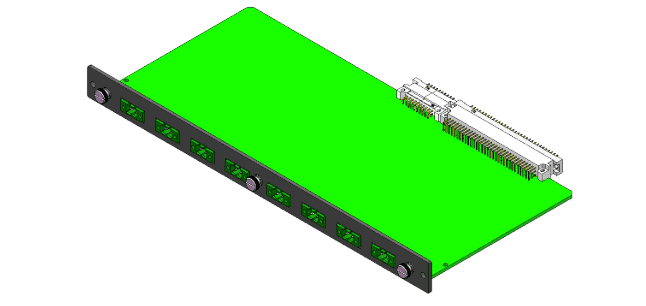
Figure 3: Auxiliary Voltage Module
Channel Module Connector(s)
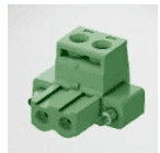
The following connector (sold separately) may be used to fabricate cables that connect to the auxiliary module:
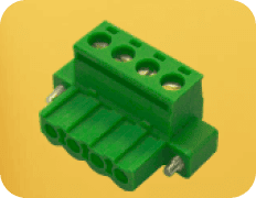
| Name | Cable Connector | Connector Illustration |
| Auxiliary Connector | Phoenix, 2-Pin, Female, 5.08 mm Arbin PN: 306130, Phoenix PN: 1777989 |
 |
Application Example
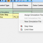
The example below introduces how auxiliary voltage inputs can be mapped (assigned) to the main I/V charge-discharge channels and implemented as a safety setting in the MITS Pro Software. The user can define the maximum and minimum value allowed during the experiment. Auxiliary voltage values can also be used within individual steps for step transitions or stopping the experiment. This cell voltage data can be compared to BMS readings, which Arbin can also record during the test.
The image below shows how the 16 auxiliary voltage inputs can be flexibly mapped (assigned) in the software with two main I/V channels. This would allow voltage monitoring for 8 cells in a battery module or pack. Any number of auxiliary voltage inputs can be mapped with an individual test channel.
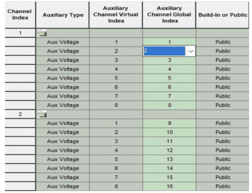
Figure 4: Mapping File
The image below shows auxiliary voltage inputs used to set a global safety limit in a test profile. The test will stop if any cell voltage reading is outside this range. Additionally, the test could be programmed to take other action instead of stopping based on these limits.
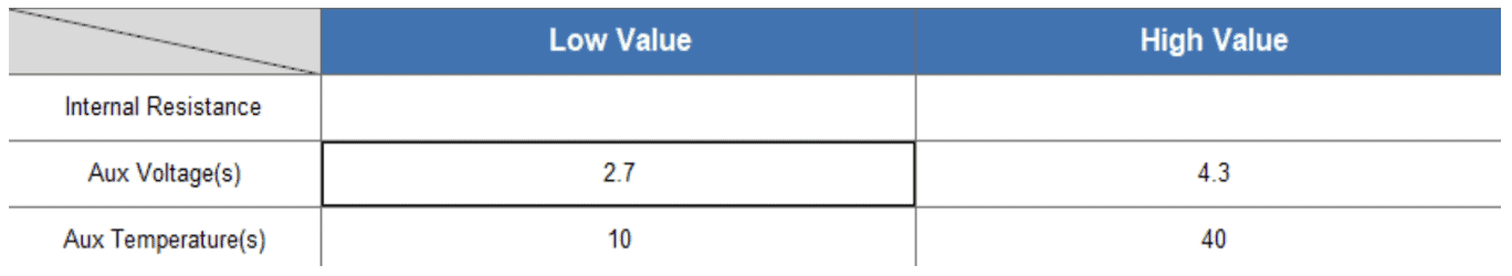
Figure 5: Auxiliary Voltage and Temperature Measurement in Global Safety
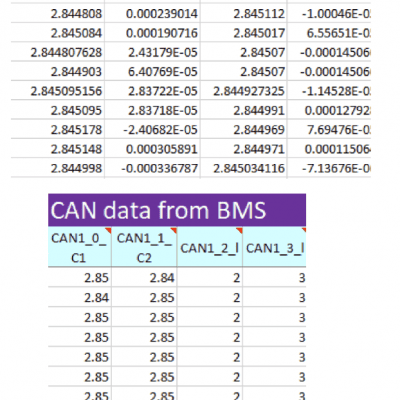
Measure Additional Cell Voltages
Data below shows how the auxiliary voltage data logged by Arbin can be compared to the CANBus data logged from BMS.
Reference Electrodes
Another common application for auxiliary voltage inputs is their use to monitor reference electrodes in a multi-electrode cell. This allows the researcher to view the impact of both the anode and cathode on the full cell performance. The images BELOW show how auxiliary voltage inputs can be used to monitor the voltage data from a reference electrode in a three-electrode cell.