


I. 목적 및 범위:
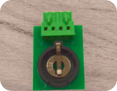
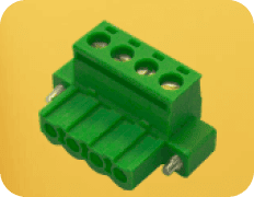
보호 회로 모듈(PCM)은 소형 가전제품부터 대규모 산업 장비에 이르기까지 광범위한 애플리케이션에서 장치를 모니터링하고 보호하는 역할을 하는 중요한 전자 부품입니다. 핵심 기능은 과충전, 과방전, 과전류, 단락과 같은 위험한 상황을 방지하여 배터리와 디바이스의 안전을 보장하는 것입니다.
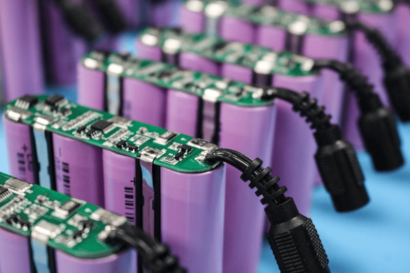
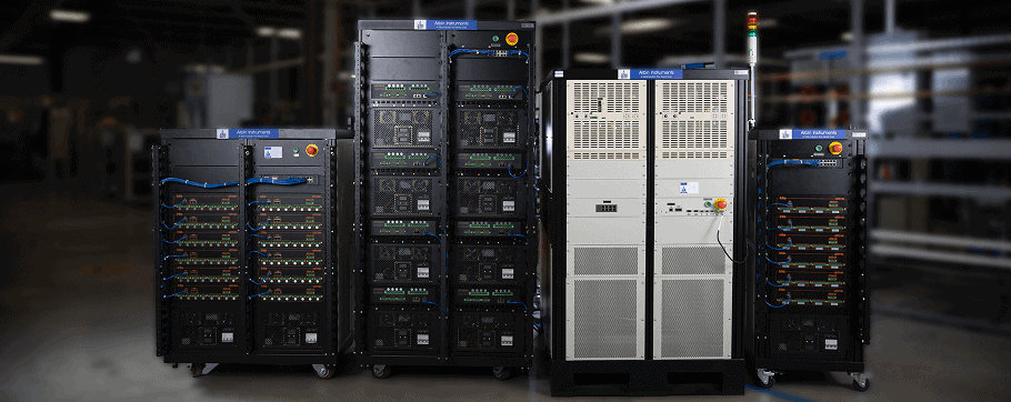
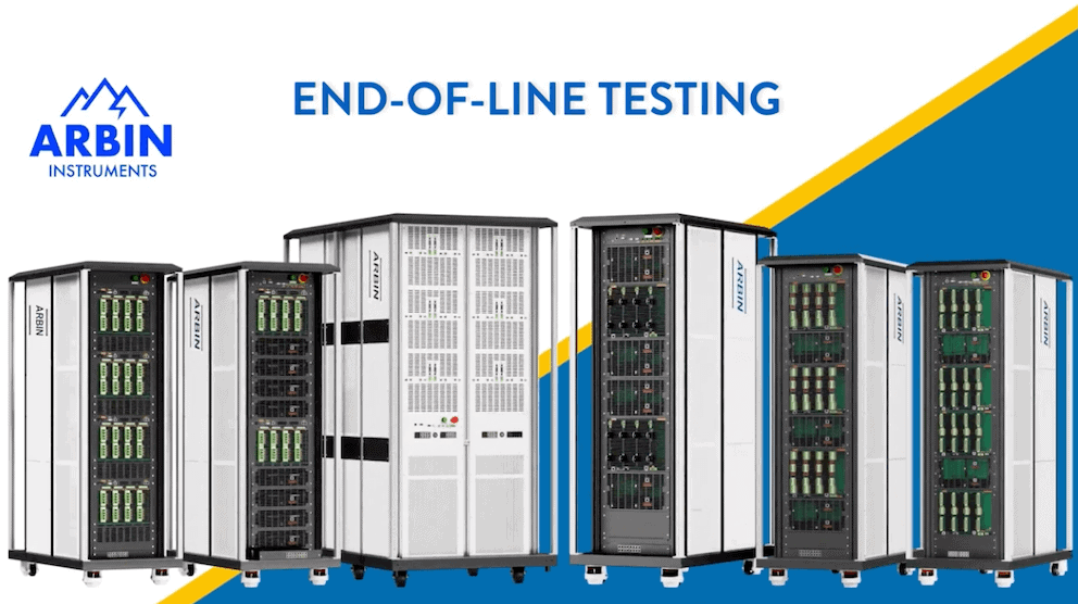
Arbin은 보호 회로 모듈(PCM)의 기능 및 신뢰성을 평가하기 위해 고객의 생산 라인에 맞춤화된 EOL(End-of-Line) 테스트 솔루션을 제공합니다. 이 테스트는 배터리의 전압 또는 전류가 설계된 최소 또는 최대 임계값을 초과할 때 PCM이 적절하게 반응하는지 확인합니다. 이러한 조건에서는 과전압, 저전압, 과전류 또는 단락 이벤트와 관련된 손상이나 안전 위험을 방지하기 위해 PCM이 자동으로 연결을 끊어야 합니다.
II. 테스트
-
절차
다음 단계는 PCM의 주요 보호 기능을 검증하기 위해 Arbin EOL 시스템을 사용하여 구현된 표준 절차를 간략하게 설명합니다. 각 단계에서는 오류 조건을 시뮬레이션하여 PCM이 설계된 대로 연결을 끊거나 복구할 수 있는지 검증합니다.
|
단계 |
테스트 항목 |
설명 |
|---|---|---|
|
1 |
과충전 방지 |
배터리 과충전을 시뮬레이션합니다. PCM이 분리될 때까지 전압을 서서히 높입니다. 출력 전류가 0A로 떨어지는 전압을 기록합니다. |
|
2 |
과충전 해제 |
가변 전원 공급 장치 전압을 천천히 낮춥니다. 전류 출력이 재개되는 전압을 기록합니다. |
|
3 |
과충전 방지 |
배터리 저충전을 시뮬레이션합니다. PCM이 분리될 때까지 전압을 서서히 낮춥니다. 출력 전류가 0A로 떨어질 때의 전압을 기록합니다. |
|
4 |
과소 충전 해제 |
가변 전원 공급 장치 전압을 천천히 높입니다. 현재 출력이 재개되는 전압을 기록합니다. |
|
5 |
충전 과전류 감지 |
충전 중 과전류 보호 기능을 확인합니다. 전류를 서서히 증가시키고 PCM이 차단을 활성화하는 값을 기록합니다. |
|
6 |
방전 과전류 감지 |
방전 중 과전류 보호 기능을 확인합니다. 방전 전류를 서서히 증가시키고 PCM이 차단을 활성화하는 값을 기록합니다. |
Arbin MITS 11 소프트웨어를 사용하여 구현합니다:
|
단계 |
테스트 이름 |
설명 |
|
|---|---|---|---|
|
|
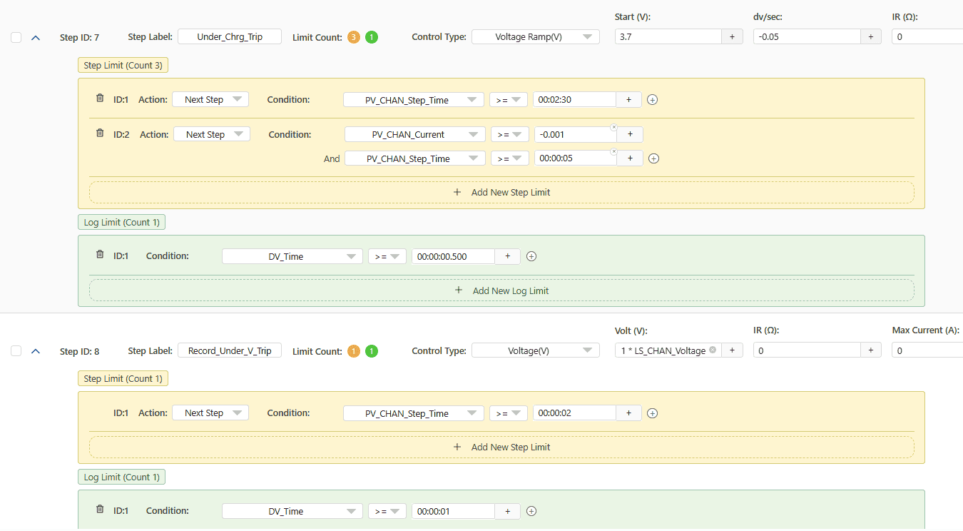
과충전 전압 테스트 |
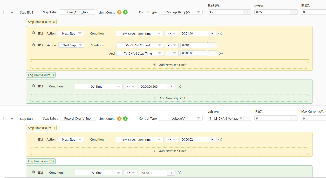
전압을 서서히 높여 배터리 과충전 상태를 시뮬레이션합니다. 전압이 사전 정의된 임계값을 초과하면 PCM은 출력을 비활성화해야 합니다. 이는 출력 전류가 다음 값으로 떨어지는 것을 관찰하여 확인합니다. 0 A. |
 |
|
2 |
과충전 복구 확인 |
전압을 천천히 낮추어 전압이 안전 범위로 돌아오면 PCM이 자동으로 출력을 다시 활성화하는지 확인합니다. 이 단계는 과충전 이벤트 후 적절한 복구 동작을 보장합니다. |
 |
|
3
|
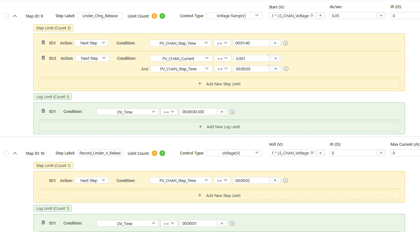
저충전 전압 테스트 |
전압을 서서히 낮추어 심방전을 시뮬레이션합니다. 전압이 안전 한계 이하로 떨어지면 PCM이 출력을 차단하여 배터리가 과방전되지 않도록 보호해야 합니다. |
|
|
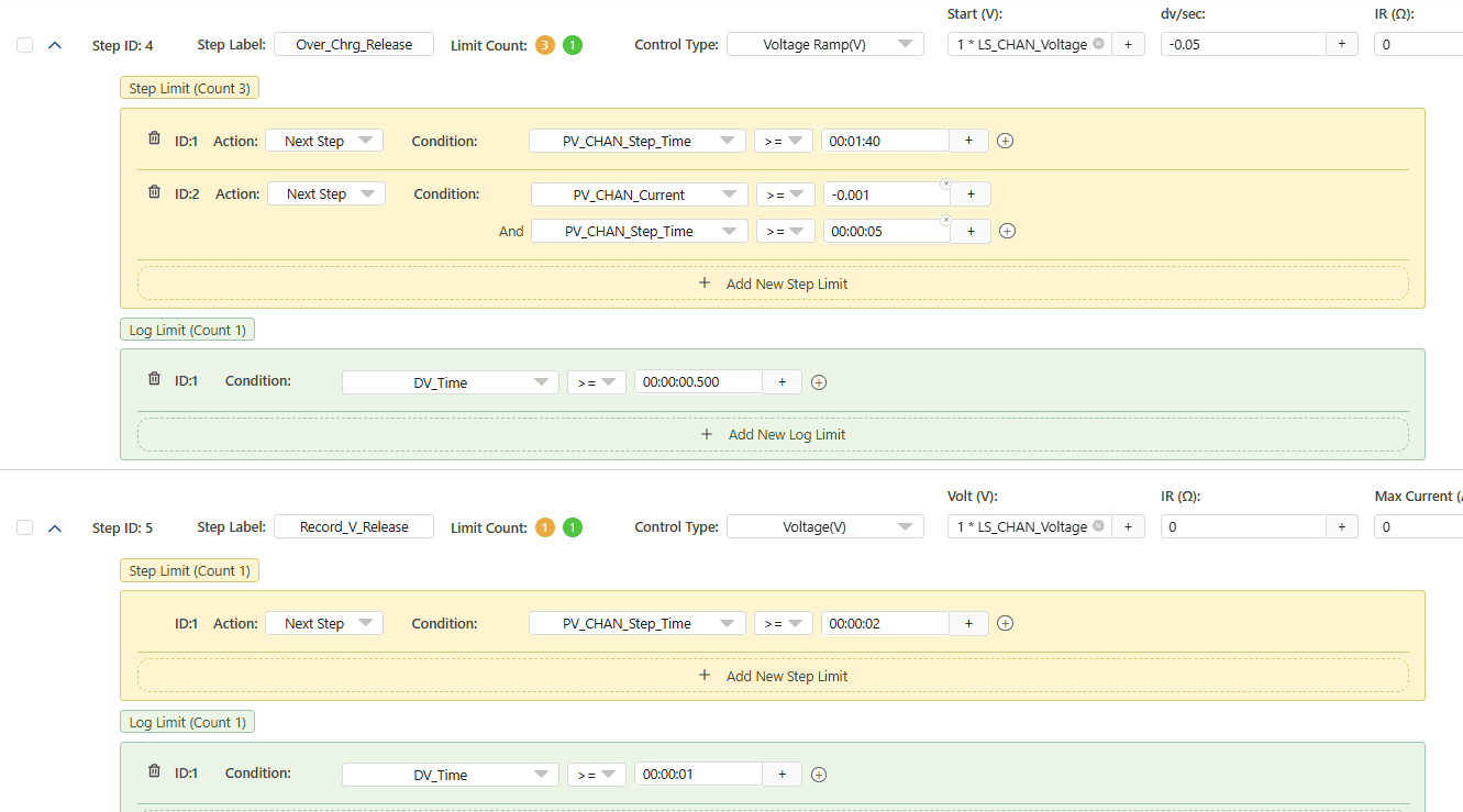
4 |
과소 충전 해제 확인 |
전압을 서서히 높여서 과소 충전 상태를 반전시킵니다. 전압이 안전한 수준에 도달하면 PCM이 출력을 복원하여 회로가 불필요하게 비활성화된 상태로 유지되지 않도록 합니다. |
 |
|
5 |
충전 과전류 보호 확인 |
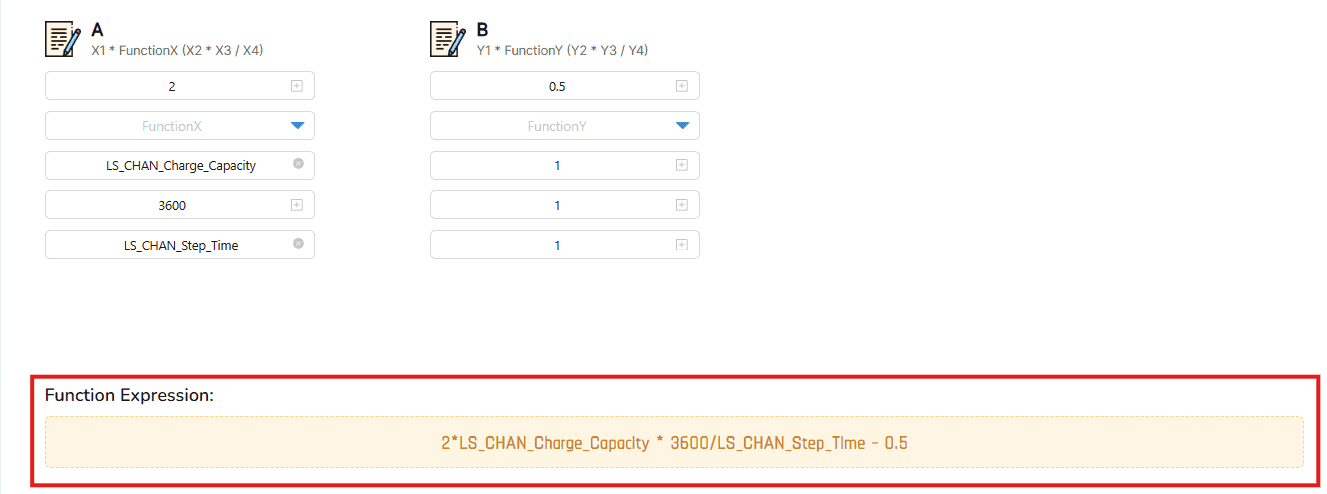
충전 전류 램프를 적용합니다. PCM은 충전 전류가 허용 한도를 초과하면 이를 감지하고 과열이나 손상을 방지하기 위해 연결을 끊어야 합니다. 참고: 과전류 값을 계산하려면(Iend), 다음 공식이 사용됩니다: 용량 로깅 방법: |
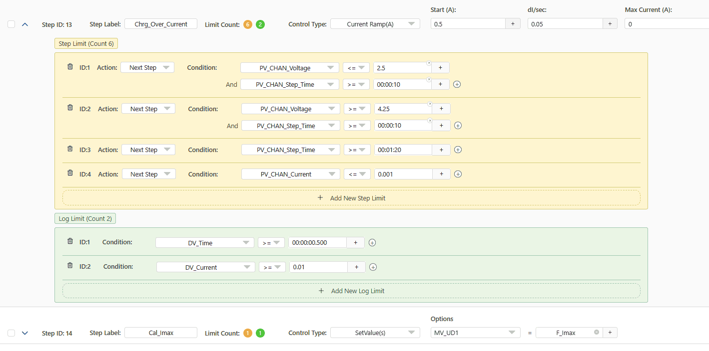  LS_charge_capacity
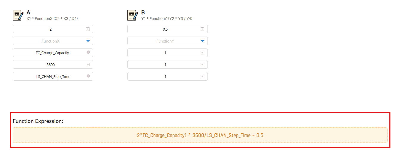 TC_Charge_Capacity
|
|
6 |
방전 과전류 보호 확인 |
과도한 방전 전류에 대한 PCM의 반응을 테스트합니다. 방전 전류가 안전 임계값을 초과하면 PCM이 출력을 차단해야 합니다. 참고: 5단계와 동일한 공식이 적용됩니다:
용량 로깅 방법: |
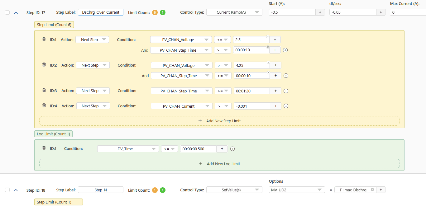 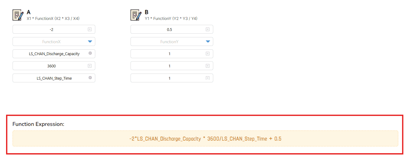 LS_discharge_capacity
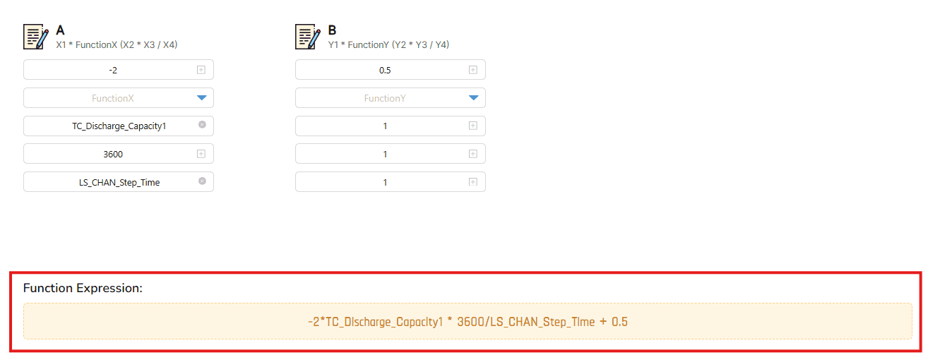 TC_discharge_capacity
|
-
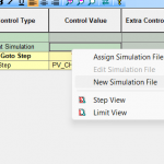
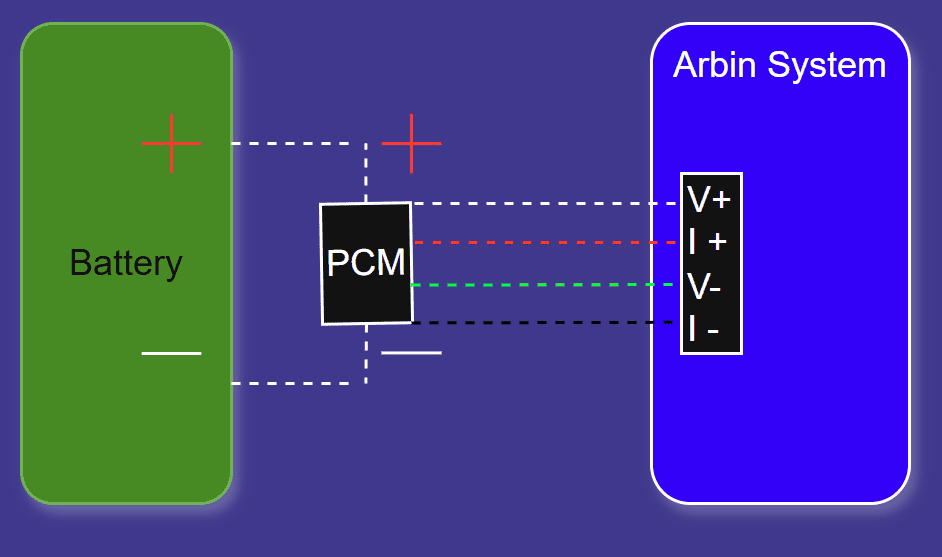
EOL 자동화 라인 통합:
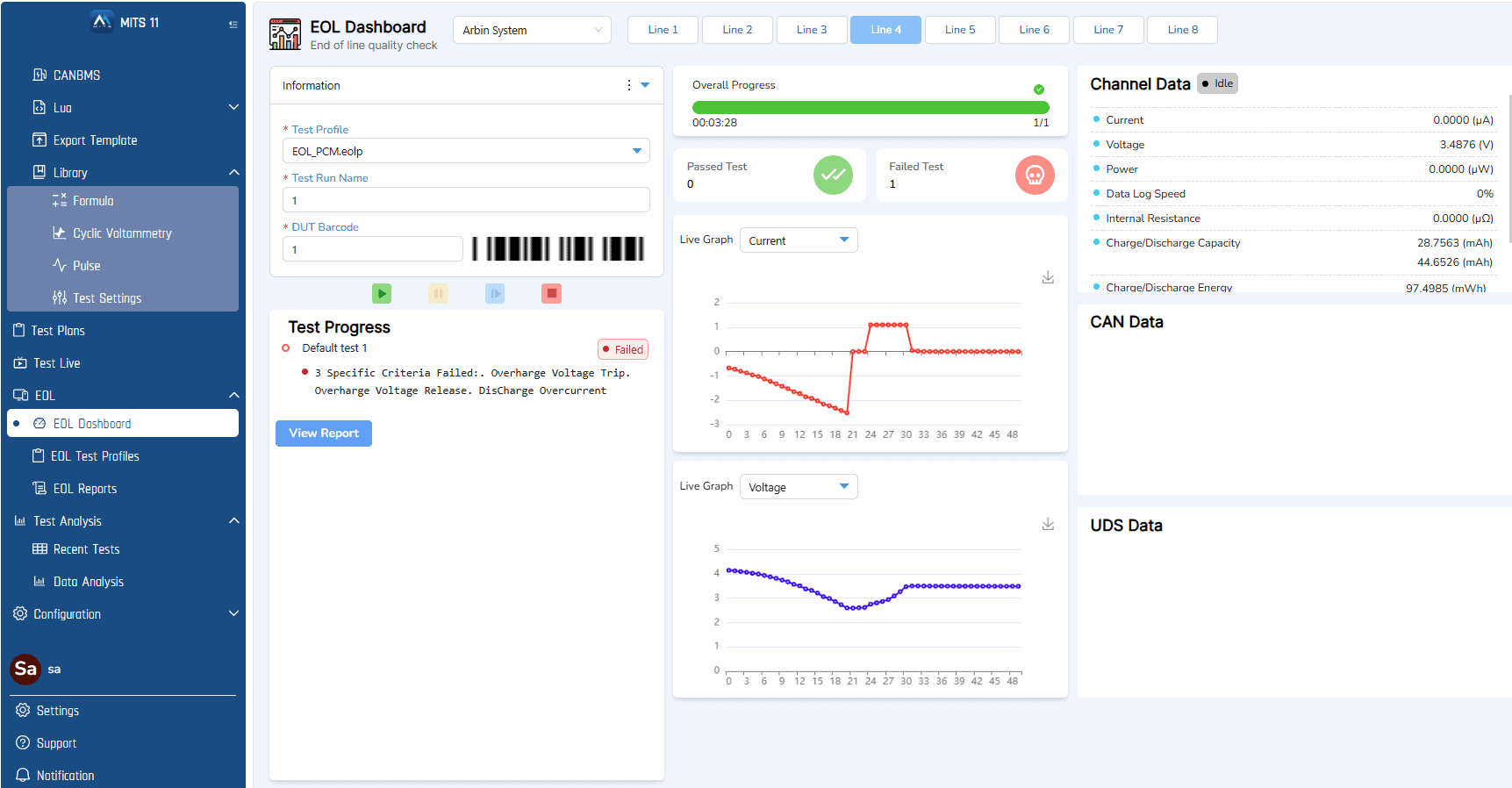
다음 이미지는 다음과 같은 구성 및 자동화 기능을 보여줍니다. MITS 11 소프트웨어를 EOL(End-of-Line) 테스트 환경에서 테스트할 수 있습니다. 이러한 설정은 위에서 설명한 PCM 유효성 검사 테스트를 구현하기 위해 특별히 설계되었습니다:
|
EOL 대시보드의 인터페이스 |
 |
|||
|
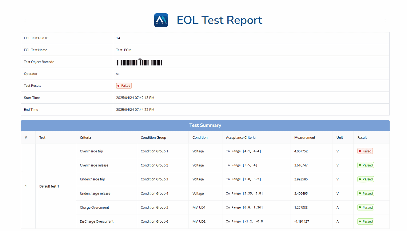
EOL 테스트 보고서 |
|
|||
|
테스트 요약 세부 정보 |
테스트 리포트 |
기준 |
측정값 |
결과 |
|
1 |
과충전 전압 |
범위 [4.1, 4.4] V |
4.007742A |
❌ 실패 |
|
2 |
과충전 전압 해제 |
범위 [3.5, 4] V |
3.6116747 V |
✅ 합격 |
|
3 |
저충전 전압 |
범위 [2.8, 3,2] V |
2.992585 V |
✅ 합격 |
|
4 |
저충전 전압 해제 |
범위 [3.35, 3.8] V |
3.406495 V |
✅ 합격 |
|
5 |
과전류 충전 |
범위 [0.8, 1.26] A |
1.257388 A |
✅ 합격 |
|
6 |
과전류 방전 |
범위 [-1.2,- 0.8] A |
-1.191427 |
✅ 합격 |
ARBIN의 EOL 플랫폼을 사용하여 6가지 중요 테스트 단계를 모두 완료한 결과, 첫 번째 기준은 실패하고 나머지 5가지 기준은 성공한 것으로 나타났습니다. 한 가지 테스트가 실패했으므로 PCM이 설계된 대로 정확하게 작동하지 않으므로 테스트에 불합격했다고 결론을 내릴 수 있습니다. 6개의 테스트가 모두 통과해야만 PCM이 통과한 것으로 간주됩니다.
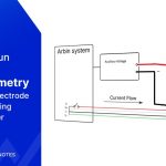
이와 같은 일련의 테스트를 통해 공장 출고 후 배터리의 실제 작동에서 PCM의 보호 로직이 제대로 작동하는지 확인할 수 있습니다. 이는 다음과 같은 경우에 필수적입니다. 배터리 수명 뿐만 아니라 사용자 안전 그리고 제품 신뢰성.
추가 지원이 필요하면 문의해 주세요: [email protected]
자세한 내용을 확인하세요: 맞춤형 배터리 팩용 보호 회로 모듈
