


-
General Description:
– Software allows the user to control a test using variables rather than concrete control values (for example, instead of using 4.2V for control, the system can use “Last Step Maximum Voltage” as the control type for the following step.
– It is also possible to use these variables in a formula to control the system (For example, “Stop the charge step when FORMULA A falls below -0.1 where FORMULA A = PRESENT CHANNEL VOLTAGE – MAXIMUM CHANNEL VOLTAGE)…..or other.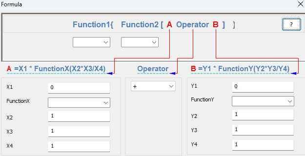
-
Function available:
ABS – Return the absolute value of a number without its sign.
ACOS – Return the arccosine of a number, in radians in the range of 0 to pi.
ASIN – Return the arcsine of a number in radians.
CEIL – Return the smallest integer that is greater than or equal to a given number.
COS – Return the cosine of an angle.
CUBIC – Return the cubic of a number
EVEN – Round a number up to the nearest even integer. Negative numbers are adjusted away from zero.
EXP – Return e raised to the power of a given number.
FACT – Return the factorial of a number.
FLOOR – Return the largest integer that is less than or equal to a given number.
INT – Round a number down to the nearest integer.
LN – Return the natural logarithm of a number.
LOG10 – Return the base-10 logarithm of a number.
ODD – Round a number up to the nearest odd integer.
RANDOM – Return an evenly distributed random number greater than or equal to 0 and less than or equal to a given positive number; return an evenly distributed random number less than or equal to 0 and greater or equal to a given negative number.
SIGN – Return the sign of a number: 1 if the number is positive, zero if the number is zero, or -1 if the number is negative.
SIN – Return the sine of an angle.
SQR — Return the square of a number.
SQRT — Return the positive square root of a number.
TAN — Return the tangent of an angle.
TRUNC — Return an integer for a number by removing the decimal, or factional, part of the number.
Operators include: + – x / %
-
Notes:
-
The Formula Feature is always enabled by default. If it is not available, it must be checked in the config file.
-
It is best to start by entering “1s” for each variable and then fill in values as needed.
-
Formulas with one ‘X’ and one ’Y’ variable should use X3 and Y3. The expression displays best with this variable placement.
-
You can import an existing formula into a new schedule: File > Import > select schedule with existing formula, and then select formula.
Example 1: A formula that uses a factor of device capacity as the end of test condition; for our example, we will use 80% of discharge capacity. F=0.8*Norminal Capacity.
During battery testing, it is important to define a stopping condition to evaluate performance degradation over time. One commonly used method is to end the test when the capacity drops to 80% of the nominal capacity.
Formula: Final_Capacity = 0.8 × Nominal_Capacity
This means the test will automatically stop when the battery’s capacity decreases to 80% of its original (nominal) value. This method provides a clear and consistent way to determine battery life and performance limits.
Step 1:
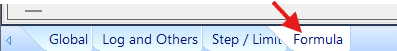
Go to Formula tab of a new schedule.
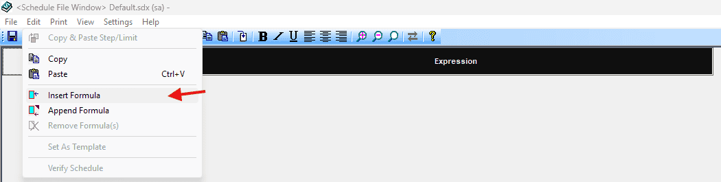
On the menu bar at the top, click Edit → Insert Formula

Step 2:
Enter the below information into each field of the formula:
Label= F_80%_Capacity → a descriptive name
X1 = 1
X2 = 1
X3 = 0.8 → this corresponds to 80% capacity
X4 = 1
Operator = *
Y1 = 1
Y2 = 1
Y3 = MV_Norminal Capacity*
Y4 = 1
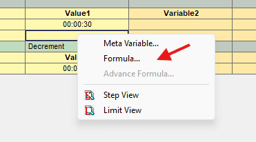
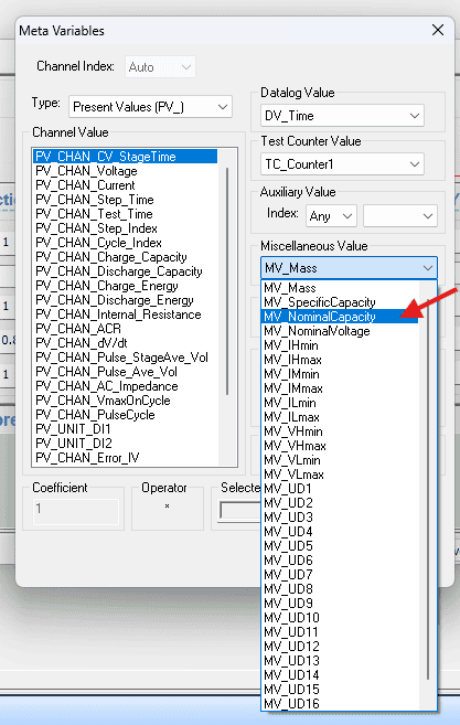
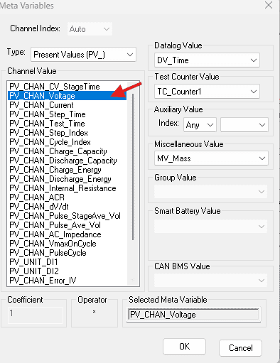
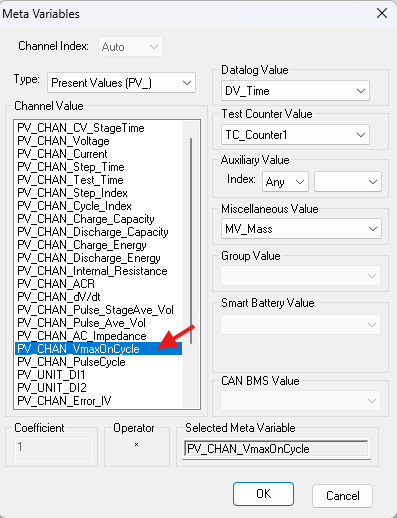
*To insert your device capacity into the formula, right click in the field for variable Y3 and click Meta variable…(as image below)

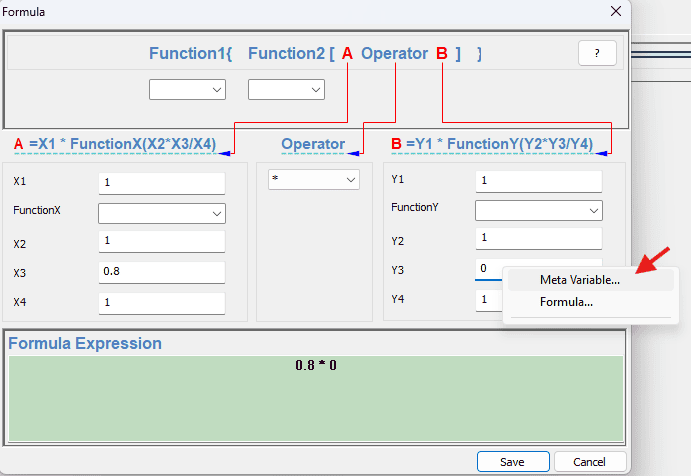
This brings up the Meta Variable dialog box. Choose MV_NorminalCapacity from the Miscellaneous Value drop-down menu.(as image below)
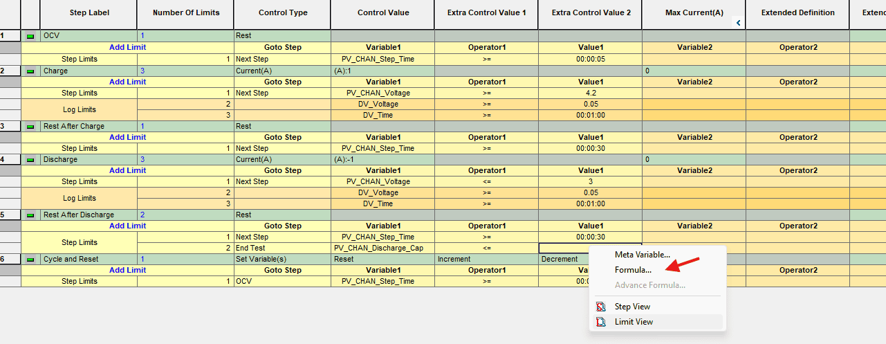
Step 3: Now that the formula is written, the next step is to insert it into a test schedule. This is done by right-clicking on a field and selecting Formula…
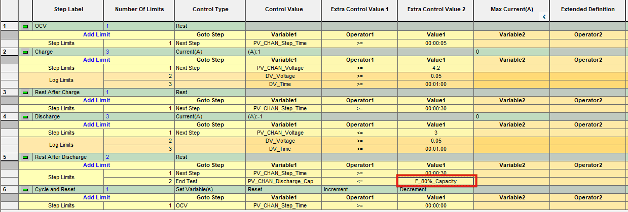
The complete test schedule to end a life cycle test when discharge capacity is 80% below.
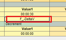
Example 2: -∆V used with Nickel chemistry to stop charging. The formula we will end with is:
F = Present Channel Voltage – Maximum Voltage during the test.
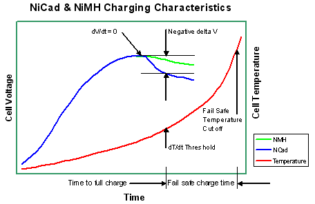
The battery voltage rises as charging progresses to a peak when fully charged then subsequently falls. This voltage drop, -delta V, is due to polarization or oxygen build up inside the cell which starts to occur once the cell is fully charged. At this point the cell enters the overcharge danger zone and the temperature begins to rise rapidly since the chemical changes are complete and the excess electrical energy is converted into heat. The voltage drop occurs regardless of the discharge level or ambient temperature and it can therefore be detected and used to identify the peak and hence to cut off the charger when the battery has reached its full charge or switch to trikle charge.
Step 1: Enter the below information into each field of the formula:
Label = F_-DeltaV → a descriptive name
X1 = 1
X2 = 1
X3 = PV_Channel_Voltage* → This references the present value of voltage on a channel
X4 = 1
Operator = –
Y1 = 1
Y2 = 1
Y3 = VmaxOnCycle* → This references the maximum voltage during a test
Y4 = 1

*To insert the variables into the formula, right-click in each field for variable X3, Y3 and click Meta variable…(as image below)
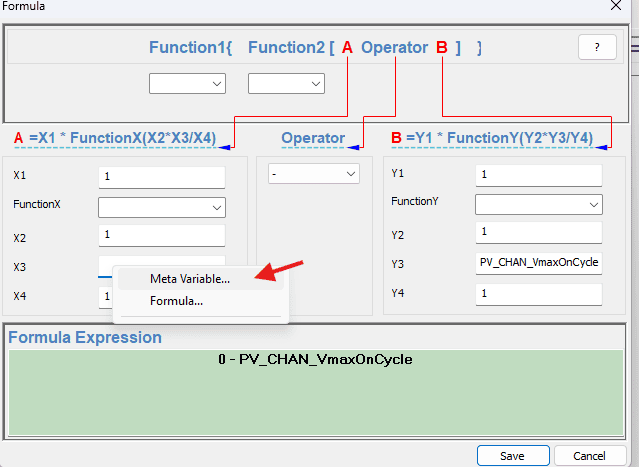
This brings up the Meta Variable dialog box. Choose PV_Channel_Voltage and PV_Channel_VmaxOnCycle for variable X3 and Y3, respectively.(as image below)
Step 2: Now that the formula is written, the next step is to insert it into a test schedule. This is done by right-clicking on a field and selecting Formula…