


Schedule and State Machine
Diagram for Step
Customers have the flexibility to edit the Schedule to customize and execute the specific tests they need for their application.
The Schedule is composed of individual units called steps, each representing a distinct phase or action within the overall testing process.
Each step operates based on the principles of a state machine, meaning it can transition from one state to another based on predefined conditions or triggers.
This state-driven approach ensures that each test can flow smoothly and logically from one phase to the next, while allowing for dynamic responses to changing conditions.
What a schedule look like
Arbin utilizes a flexible Schedule system to control and organize the sequence of battery tests. Within this schedule, users have the ability to specify various control types, which determine the exact type of test to be conducted-whether it's charging, discharging, or cycling, among others.
Additionally, users can configure log conditions to define the specific parameters and intervals at which data is recorded, ensuring that only the most relevant data is logged for further analysis.
This system provides users with a customizable and precise framework to tailor their battery testing procedures to meet specific testing goals.
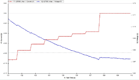
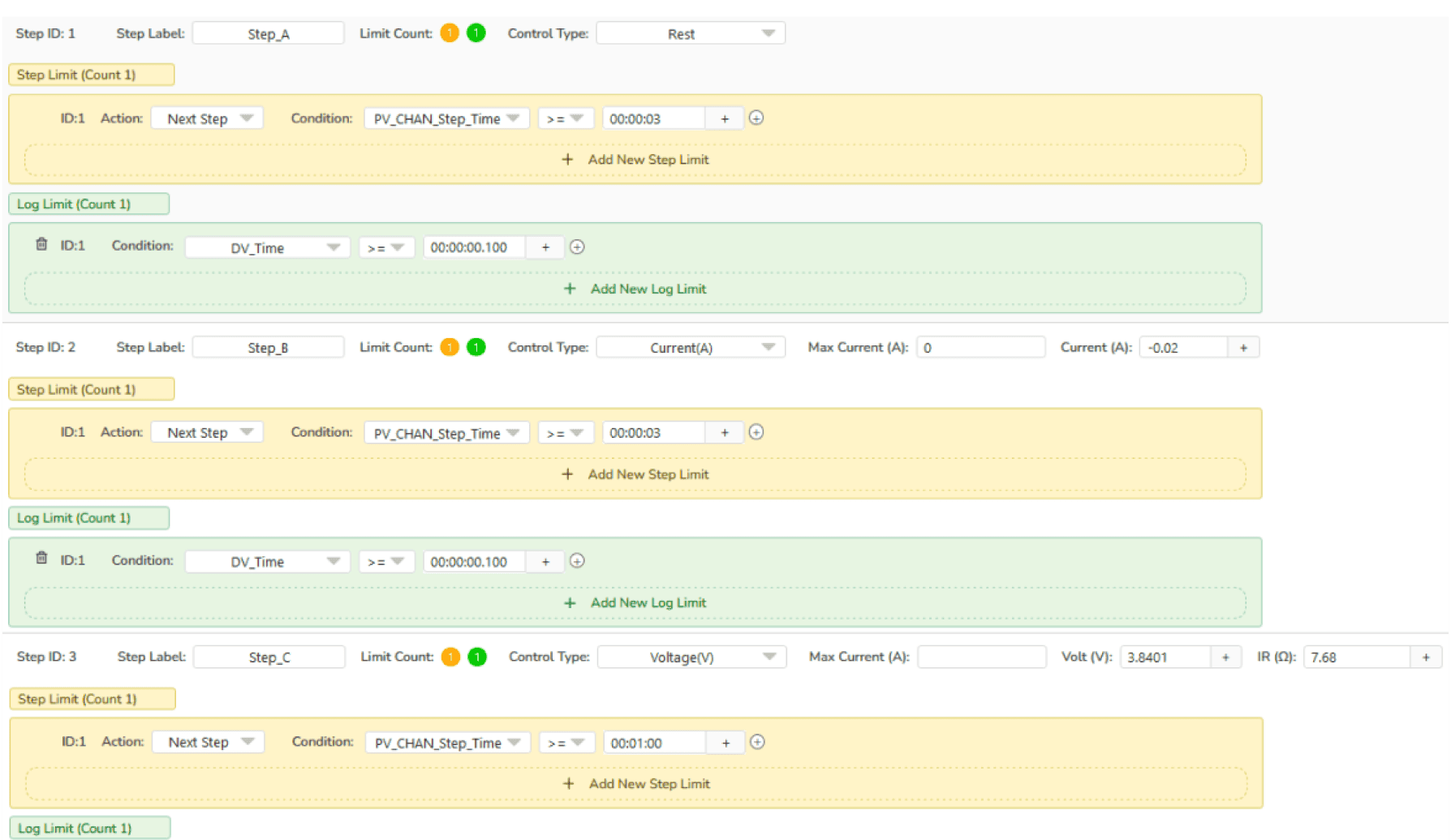
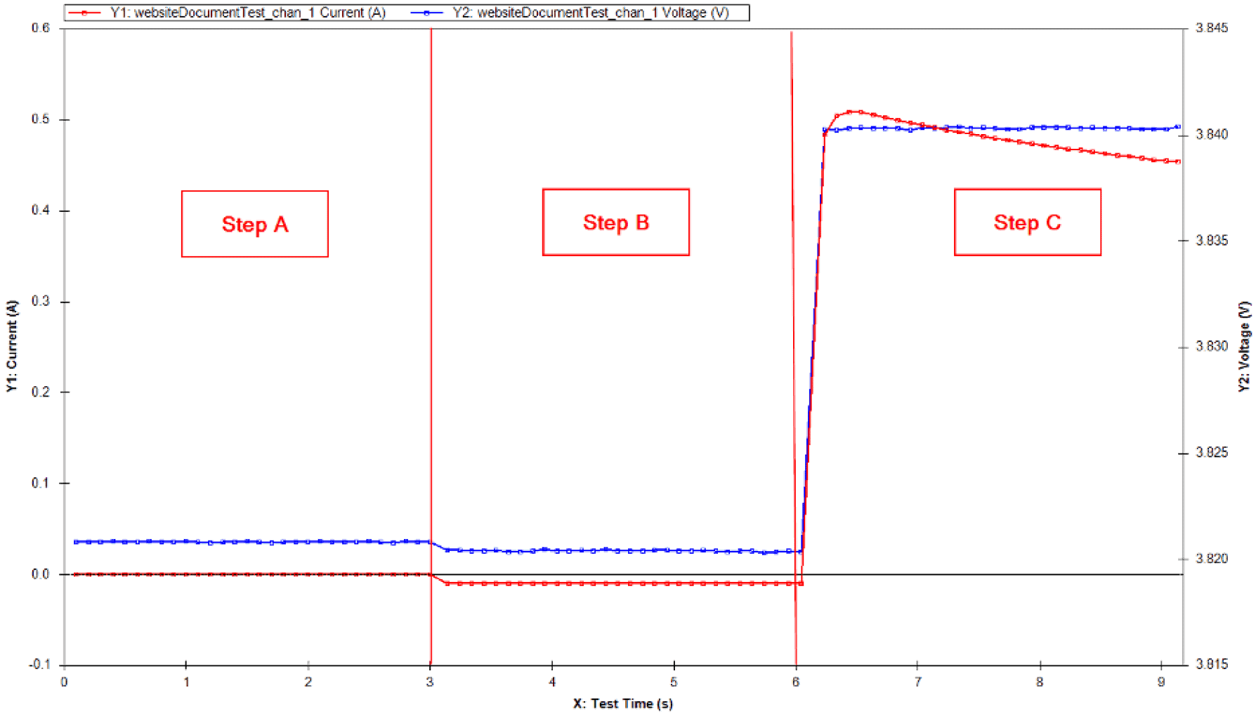
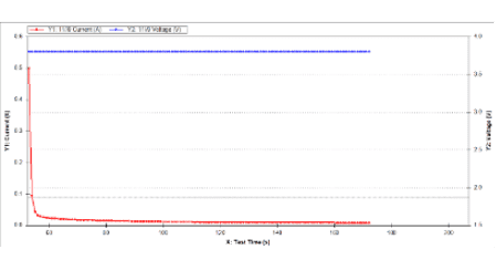
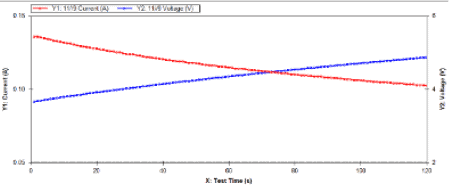
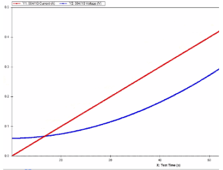
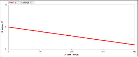
Example of running a test:
State Machine Diagram of Step

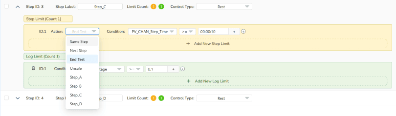
- Stay at the same step.
- Restart at the same step
- Go to the next step.
- Jump to another step.
- Finish the test.
- End Test
- Unsafe

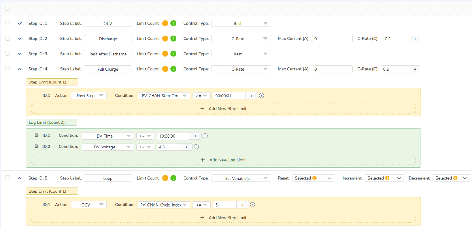
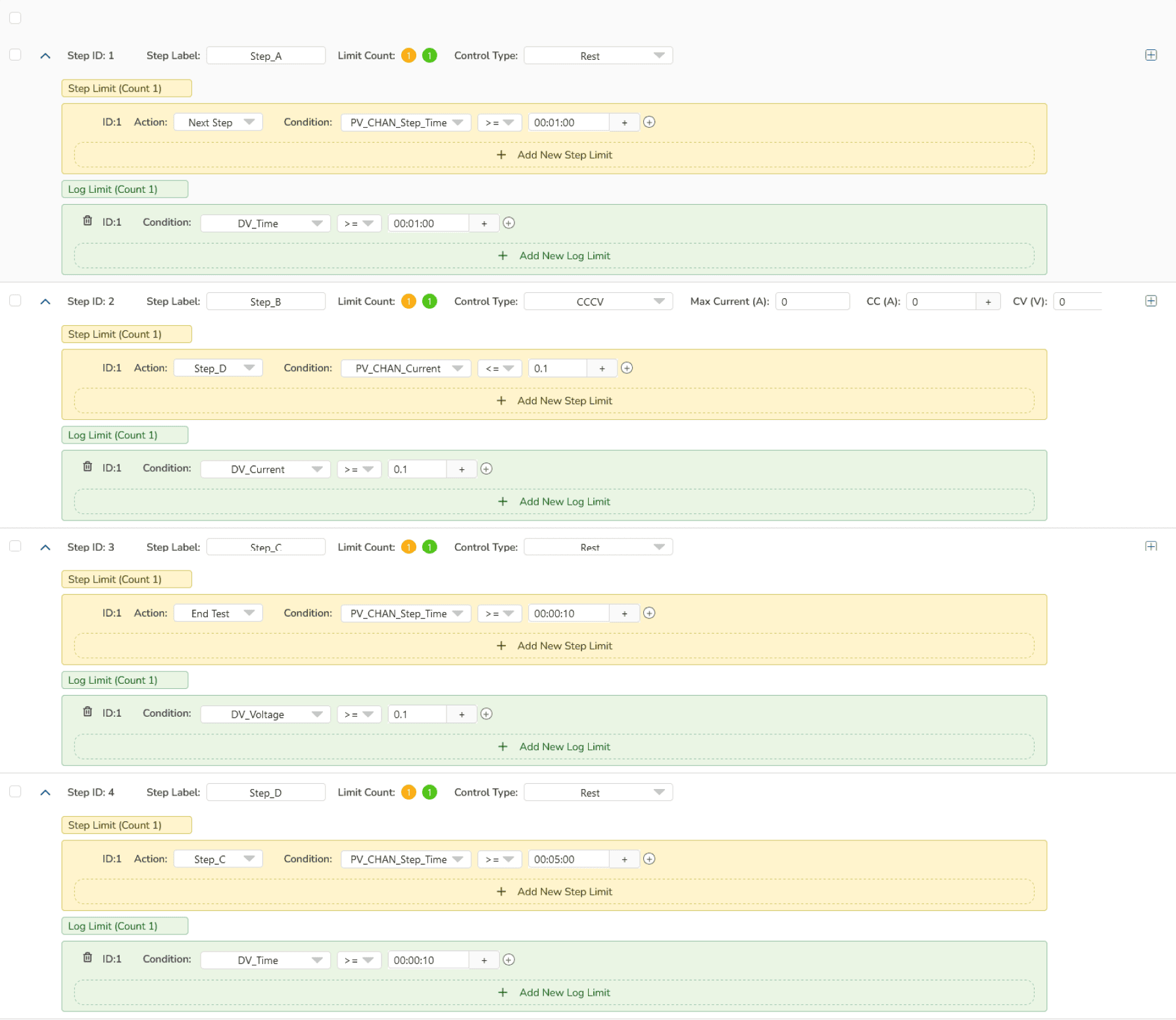
Example Schedule:

Sub-Schedule (Subroutine) Merkmal
 Feature")
Introduction to Sub-Schedule
We have integrated the concepts of encapsulation and reusability into our Schedule and Sub-Schedule methods, delivering a powerful solution that enhances efficiency and flexibility in your development process.

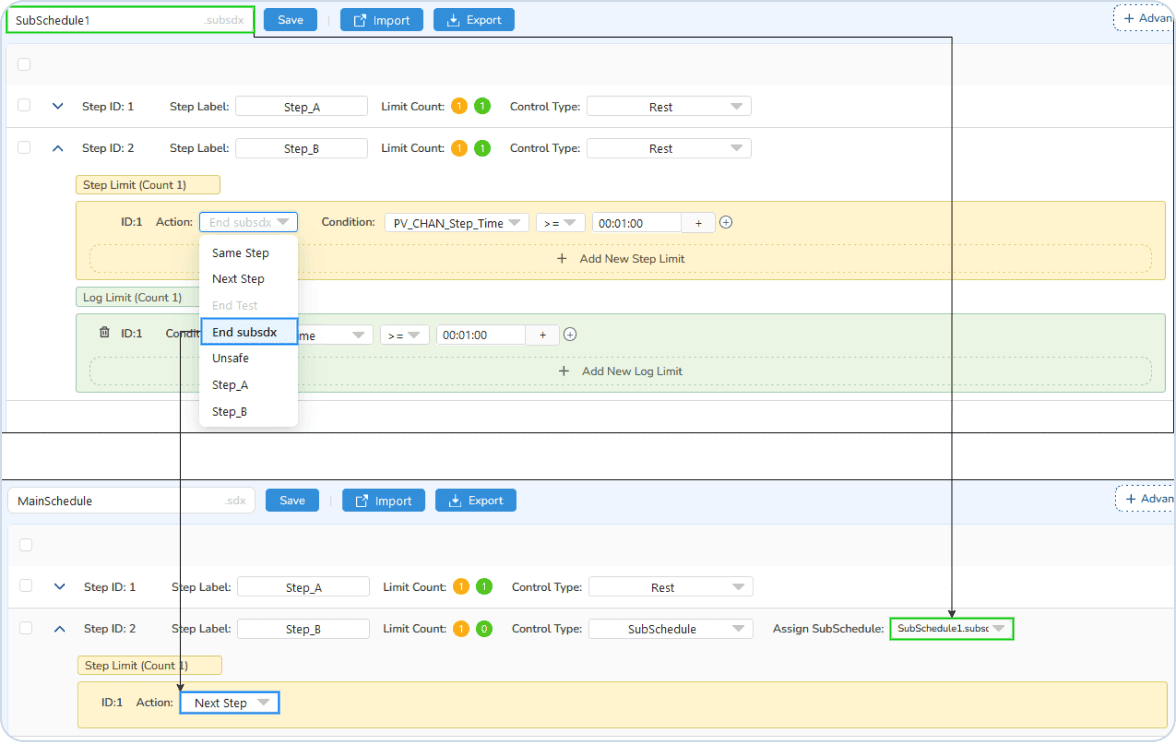
The left is main Schedule and the right are Sub-Schedules
Advantages
Modular Testing Routines
With Sub-Schedule, you can create reusable testing routines that can be easily put into your main schedule, like in programming. This allows you to avoid redundancy and maintain cleaner, more organized schedules.
Flexibility
Quickly adapt your testing protocols by modifying Sub-Schedules without the need to overhaul the entire main schedule. This flexibility is essential for R&D environments where testing parameters may frequently change.
Streamline Test Design
Reuse commonly performed test sequences to create new battery test recipes faster and more efficiently, reducing the need for repetitive setup.
Enhanced Version Control
Maintain better organization and oversight of test variations by isolating and reusing critical components within tests, ensuring consistency across different test versions.
Simplified Workflow
Easily integrate previously validated test segments into new tests, enabling smoother test creation while maintaining the accuracy of complex battery testing protocols.
Simplified Managed Tests
Reuse commonly performed test sequences to create new battery test recipes faster and more efficiently, reducing the need for repetitive setup.
Reusability
Easily integrate previously validated test segments into new tests, enabling smoother test creation while maintaining the accuracy of complex battery testing protocols.
Adaptability
Reuse commonly performed test sequences to create new battery test recipes faster and more efficiently, reducing the need for repetitive setup.
Feature & Spec
Sub-Schedule Editor

We have a Sub Schedule folder in the Schedule Editor. The way to create a Sub Schedule is the same as creating a Schedule
Implement Sub-Schedule
Assignment
Here is how you assign sub schedule
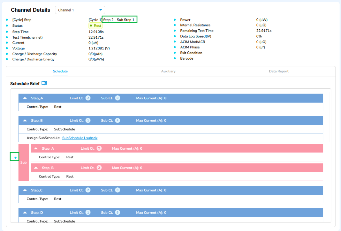
Monitor Test (Monitor & Control)
Channel View in the Monitor & Control window will also show whether the test is in a SubSchedule step.
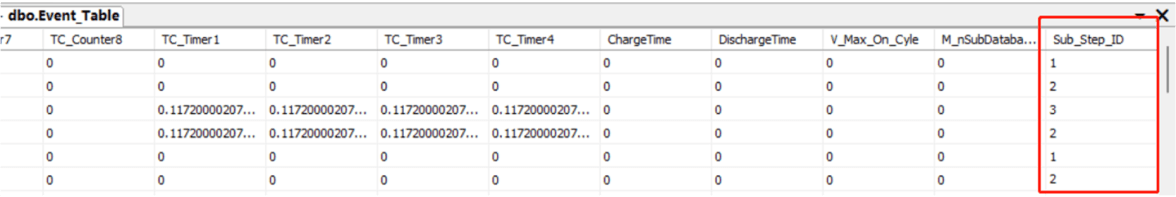
Data Query
A new field in SQL will be added, "Sub_Step_ID" to the database Event_Table, Resume_Table, and other related database tables so that users may view the corresponding data when querying results.
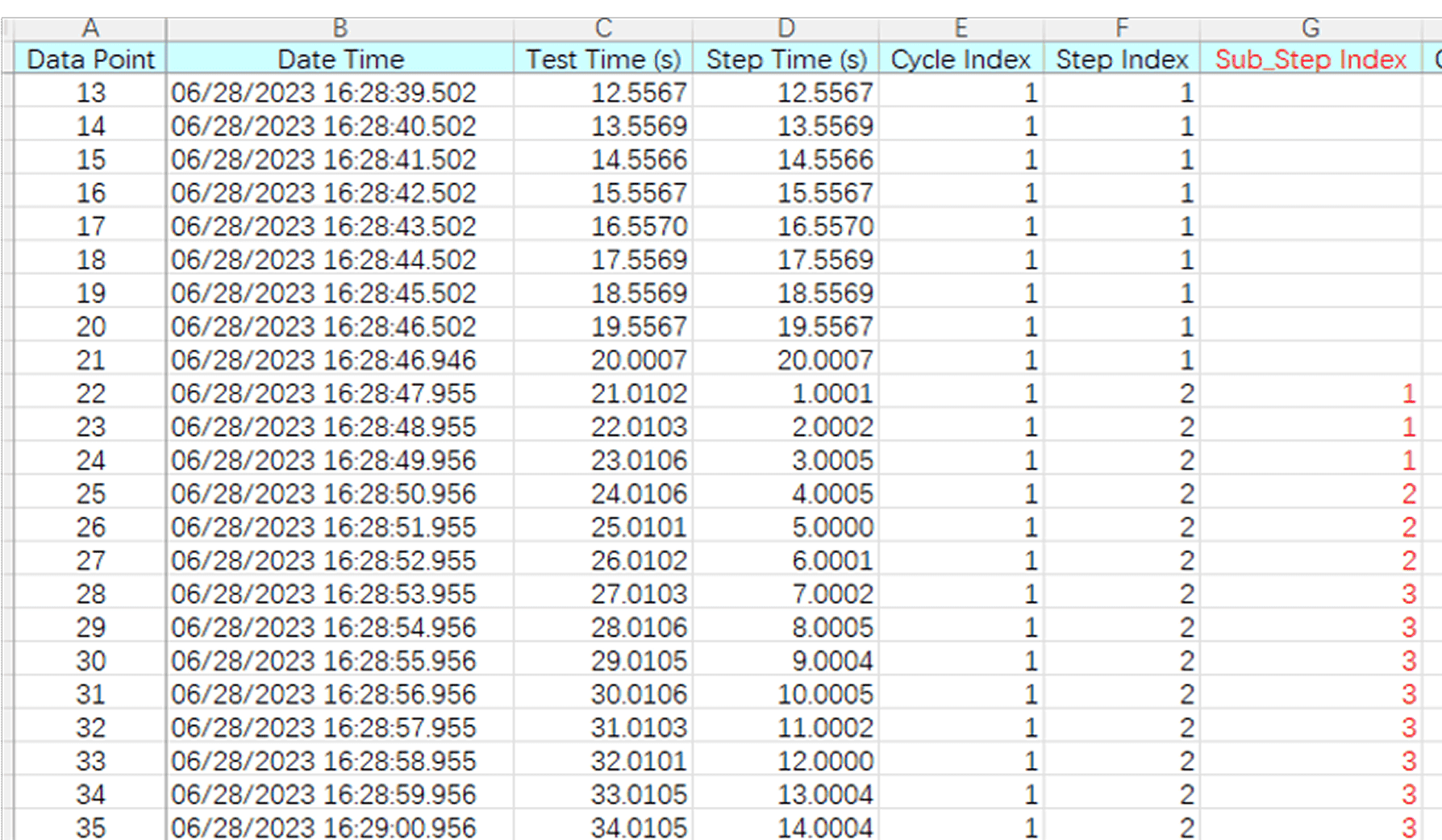
Viewing Data
When exporting data to Excel or CSV file, a new column for SubSch Step has been added.
List of control types
- None
Control Method:
- The battery will be in an open-circuit state, with the relay turned off.
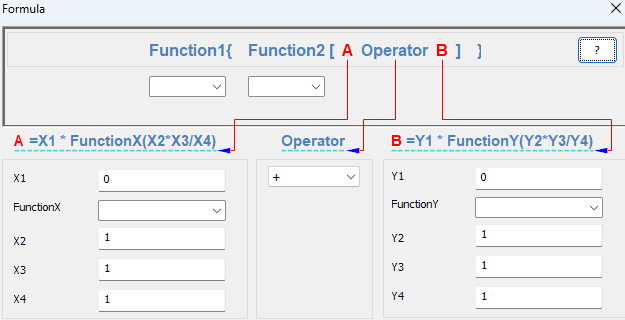
- The current value is measured in amperes (A). It can be a numerical value, where '1A' indicates 1 ampere of charging and '-1A' indicates 1 ampere of discharging. Additionally, the control value can be a variable or a formula.
Control Method:
- The battery is connected in series with a constant current source, outputting/inputting a constant current, with the current value set by the control value.
- The value of the voltage is measured in volt (V). It can be a numerical value, or it can be a variable or a formula.
Control Method:
- The battery is connected in parallel with a constant voltage source, outputting/inputting a constant voltage, with the voltage value set by the control value.
- Some channel boards are equipped with hardware-based constant voltage sources, whereas others rely on software-based PID control to implement a digital constant voltage source.
- Charging or discharging at a current that will fully charge or discharge the battery in one hour. For example, for a battery with a capacity of 1000mAh, 0.03C means charging or discharging at a current of 0.03 * 1000mA = 30mA.
Control Method:
- The battery is connected in series with a constant current source, outputting/inputting a constant current, with the current value set by the control value.

- The power value is measured in walt (W). It can be a numerical value, or it can be a variable or a formula.
Control Method:
- Input constant power to/from the load.
- Start(A): Initial value in ampere (A).
- dI/sec: Rate of current change per second.
Control Method:
- Set the output/input current as a linear variable, achieving control through setting the initial value and rate of change.
- Start(V): Initial value in voltage (V).
- dV/sec: Rate of voltage change per second.
Control Method:
- Set the output/input voltage as a linear variable, achieving control through setting the initial value and rate of change.
- Start(A): Initial value in ampere (A).
- dI/stair: Rate of current change per stair.
- Stair Time: Duration of the step, in seconds.
Control Method:
- Set the output/input current step, achieving control through setting the initial value, step change, and step duration.
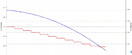
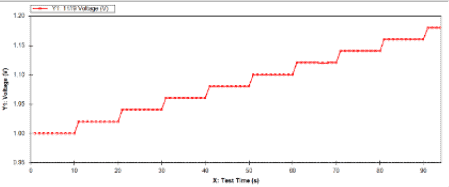
- Start(A): Initial value in volt (V).
- dV/stair: Rate of voltage change per stair.
- Stair Time: Duration of the step, in seconds.
Control Method:
- Set the output/input voltage step, achieving control through setting the initial value, step change, and step duration.
- Reference a current simulation file (.txt).
- Options to repeat log points and whether each current value requires logging two points are available.
Control Method:
- Through the simulation file, illustrate simulated output/input current values, which must include timestamps and control values.
- Amplitude: The amplitude of the pulse, in amperes (A).
- ms: Pulse duration, in milliseconds (ms).
- Offset: The offset of the pulse.
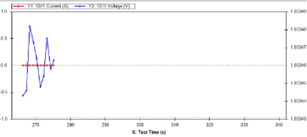
Control Method:
- Utilize positive and negative pulses output to the load and calculate the internal resistance by recording the voltage change values.
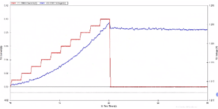
- CC: Current value during the CC phase, in amperes (A).
- CV: The voltage value during the CV phase, in volts (V).
- IR: The internal resistance value, in ohms (Ω).
- CC and CV can be numbers, variables, or formulas, while IR only supports numbers.
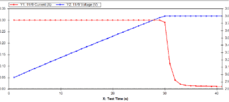
Control Method:
- Utilize CCCV to charge/discharge the load. Before the load reaches the target voltage, charge/discharge at a fixed current using the CC control value. Once the load reaches the target voltage, charge/discharge at a fixed voltage using the CV control value.
There are 3 options available:
- Normal: Normal mode, pauses the test when it reaches this step
- ACIM: Alternating Current Impedance Mode
- T_Chamber: Temperature Control Chamber Mode
Control method:
- Upon entering this pause step, you can either pause simply, measure alternating current impedance, or set up the temperature control chamber.
Three control options:
- Reset: Reset the variable to 0.
- Increment: Increase the variable value by 1.
- Decrement: Decrease the variable value by 1.
Control Method:
- Provide users with the ability to operate on declared variables, including resetting, incrementing, and decrementing. Users can use these variables to set step limits or log limits, enhancing the flexibility of the schedule design.
- IR: Internal resistance value, measured in Ohms.
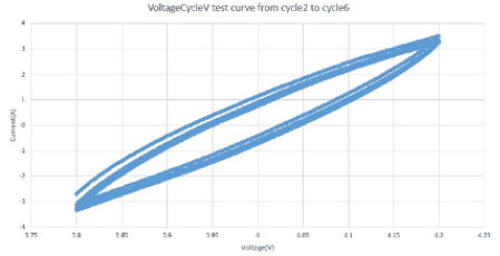
- Additionally, reference a pre-set cyclic voltage file.
Control Method:
- Conduct cyclic testing on voltage, allowing for the definition of start voltage and target voltage by the user.
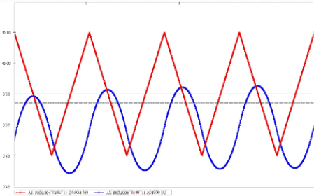
- Reference a pre-set cyclic current file.
Control Method:
- Conduct cyclic testing on current, allowing for the definition of starting current and target current by the user.
- Reference a power simulation file (.txt).
- Options include whether to log points repeatedly and whether each current value needs to log two points.
Control Method:
- Through the simulation file, simulate the output/input of current, voltage, and power values, with the file containing timestamps and control values.
- Referencing a load simulation file (.txt)
- Options to repeat log points and whether each current value requires logging two points are available.
Control Method:
- Through the simulation file, simulate output/input load values are described. The file must include timestamps and control values.