 English
 简体中文
 한국어

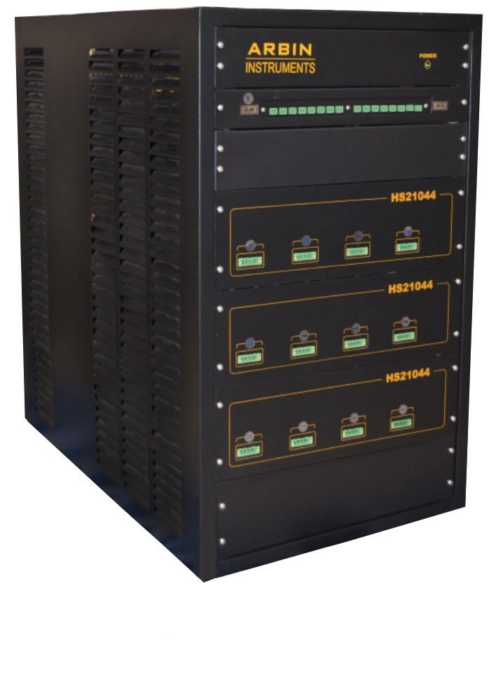
High Speed Pulse Testing System
HSP High Speed Pulse Tester (HSP)
Multi-stage current pulses as short as 100 µs, with rise times under 10 µs, on independent channels running at the same time. Simulate GSM, CDMA, iDEN and GPRS pulse profiles, or build any custom profile of 2 to 30 stages for telecom, IoT, medical, power-tool and consumer electronics batteries. The same channels also run standard laboratory cycling, DCIR and three-electrode tests.
100 µs
Minimum pulse stage width
2 – 30
Stages per user-defined pulse profile
< 10 µs
Current rise time
4 – 24
Independent channels per system
Accuracy you can audit
Measurement accuracy held across all voltage and current ranges, with precision published as a separate specification.
Independently verified
Designed and manufactured under an ISO 9001:2015-certified quality system, supported by an ISO/IEC 17025-accredited testing and calibration laboratory.
35 years of instrumentation
Founded 1991. Arbin reinvests 30% of profits into R&D, funding the precision architecture provided with every Arbin test station.
Built for any lab
Scalable channel density in a compact, air-cooled footprint, with open Python and C# API for the automation you already run.
Highlights of the HSP High Speed Pulse Tester
Four hardware decisions that let a cell see the pulse your device actually draws, not a smoothed-out average of it.
100 µs Pulse Stages
2 to 30 stages, 20 µs increments
Build the exact pulse your device draws
Define profiles of up to 30 stages, each as short as 100 µs and adjustable in 20 µs steps.
Use GSM, CDMA, iDEN and GPRS shapes, or a custom profile for medical devices, power tools and consumer electronics. The profile repeats until your termination condition is reached.
Fast Rise Time
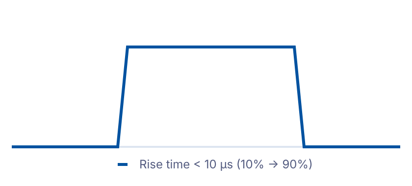
10% to 90% in under 10 µs
Square pulses, not rounded ones
Current reaches 90% of its set value in under 10 µs on the 5 A and 100 mA circuits, and under 50 µs on the 10 A circuit.
Even a 100 µs stage delivers its full amplitude for nearly its whole width.
True Bipolar Circuitry
cross-zero linearity
Charge to discharge in one stage step
The bipolar design moves through zero linearly, with no switching time between charge and discharge.
Profiles can alternate polarity stage to stage without gaps in the waveform. Each channel works as an independent potentiostat/galvanostat.
Up to 4 Current Ranges
100 µA to 10 A, by model
Bursts and standby current on one channel
Up to four current ranges per channel, so the same channel can pulse amps during a transmit burst and measure milliamp or microamp current in between.
Current accuracy is 0.04% of each range.
Two Operating Modes on Every Channel
Pulse Mode runs repeating multi-stage profiles down to 100 µs. Normal Mode runs conventional schedules with steps from 5 ms. Choose per test, on the same hardware.
Pulse Mode
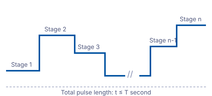
Each channel runs one pulse profile that repeats until the termination condition is reached. A window of data is logged every second.
- Pulse independency
- One profile per channel
- Maximum pulse stages (n)3
- 30
- Minimum pulse stage width
- 100 µs
- Stage width increment
- 20 µs
- Control type
- Current
- Data logging rate
- 2 points per stage
- Interval between logged pulses
- One pulse every second4
Best when the test subject is the device's real load: telecom transmit bursts, power-tool triggers, medical device pulse trains.
Normal Mode
Conventional charge/discharge schedules: constant current, voltage, power and load, ramps, staircases, DCIR and cycling.
- Current rise time1
- <10 µs (5 A, 100 mA)
<50 µs (10 A) - Current and voltage resolution
- 16-bit
- Measurement precision
- 0.02% FSR
- Voltage clamp2
- Individual, per channel
- Standard step data logging
- 2,000 points/s per PC
- Minimum step time
- 5 ms
- Time measurement resolution
- 10 µs
Best when the same cells also need lab-scale cycling, DCIR, three-electrode or quality-control testing.
- Time required for current output to get from 10% to 90% of requested value.
- Voltage clamp accuracy tolerance is 0.2% FSR.
- Pulse must contain at least one stage with minimum pulse width.
- Pulse profile repeats continually until termination condition is reached. A window of data (at 2 points per stage) is logged every second.
Applications and Test Methods
Built for batteries whose real load is a fast, repeating pulse, while still covering standard laboratory testing.

Telecom and connected devices
GSM, CDMA, iDEN and GPRS pulse simulation for mobile phones, tablets, GPS units, smart watches, IoT and smart-home devices.

Power tools, medical and military
Custom high-speed profiles that reproduce real-world loads, where a constant-current test misses the stress the cell actually sees.

Standards and qualification
Suitable for test protocols such as UL1642, UN38.3, IEC62133, GB/T 18287-2000, MOTO and Apple.

Lab-scale R&D and QC
Anode, cathode and separator R&D, three-electrode measurement, DCIR, lithium-ion and supercapacitor testing, production and quality inspection.
Supported Test Methods
Pulse and simulation
- User-defined current pulse profiles
- GSM / CDMA / iDEN / GPRS pulses
- Current and power simulation from ASCII data
- DC internal resistance (10-pulse train, 1 ms)
Cycling
- Constant current, voltage, power and load
- C-rate charge and discharge
- Rest with open-circuit voltage measurement
- Lithium-ion and supercapacitor cycling
Electrochemical
- Cyclic voltammetry (Voltage Cycle)
- Current and voltage ramps
- Current and voltage staircases
- Three-electrode measurement
Models, Voltage and Current Ranges
Four models cover bipolar ±5 V work and unipolar cells up to 10 V, with up to four current ranges per channel.
| Model | Voltage range | Current ranges per channel | Current accuracy (0.04%) | Min. voltage at max. current | Max. power per channel |
|---|---|---|---|---|---|
| HSP ±5V 100mA | −5 to 5 V | 100 mA · 10 mA · 100 µA | ±80 µA · ±8 µA · ±8 nA | −5 V @ 5 A | 0.5 W |
| HSP ±5V 5A | −5 to 5 V | 5 A · 500 mA · 20 mA · 1 mA | ±4 mA · ±400 µA · ±16 µA · ±0.8 µA | −5 V @ 5 A | 25 W |
| HSP 5V 10A | 0 to 5 V | 10 A · 500 mA · 20 mA · 1 mA | ±8 mA · ±400 µA · ±16 µA · ±0.8 µA | 0 V @ 10 A | 50 W |
| HSP 10V 5A | 0 to 10 V | 5 A · 500 mA · 20 mA · 1 mA | ±4 mA · ±400 µA · ±16 µA · ±0.8 µA | 0 V @ 5 A | 50 W |
Software and Safety
Build, preview and run pulse profiles in Arbin software, with safety limits on every test and every step.
Software Control
Create a pulse profile stage by stage, preview it, then run it. Pulse steps sit alongside every standard control type in the same schedule.
- Current Pulse control type applies any user-defined pulse profile
- Current and power simulation from external ASCII data streams
- DC internal resistance: 10-pulse train with 1 ms pulse width
- Current, voltage, power, load, C-rate, ramps, staircases and cyclic voltammetry
- End conditions on time, voltage, current, capacity, energy, ΔV, dV/dt, formulas and meta-variables
- Data exports to Microsoft Excel, with the Arbin Excel Data Pro macro included
Safety Architecture
Protection at the channel, board and power-supply level, plus software limits that check every control value before a test starts.
- Multiple levels of fusing at channel/board and power-supply level
- Over-charge/discharge, system watchdog and over-temperature protection
- Per-channel voltage clamp against over and under charge or discharge
- Software safety limits for whole tests and for individual steps
- Every test begins with a built-in safety check of all control values
Auxiliaries and Optional Accessories Available to Enhance Testing
Thermal and Environmental
- Auxiliary temperature: thermocouple or thermistor inputs that record temperature and can control the test schedule
- MTCI chamber interface: Arbin software turns a third-party chamber on and off and sets its temperature
Electrochemical Impedance Spectroscopy
- An approved EIS module, interfaced with the system
- Automatically shared across all channels
Auxiliaries
- Auxiliary voltage: additional reference electrodes to measure voltage
- Digital I/O: on/off signals to and from external devices
- Analog I/O: control any device on a 0(2)–10 V signal
- Auto-calibration with a digital multimeter (sold separately)
- UPS for the PC, so tests resume after brief power outages
Holders & Fixtures
- Battery holders for coin, cylindrical, flat/pouch cells and more
- Optional battery holder system mounted on the side of the chassis
- Standard 6 ft 4-pin I/V cables with lugs or alligator clips
of battery test instrumentation, founded 1991
certified quality management system
accredited electrical calibration laboratory
multi-stage pulses with simultaneous data logging
Tell us about your pulse profile
Share your cell type, pulse shape, stage widths, peak current and channel count. An Arbin sales engineer will recommend the right HSP model and chassis.
