


Purpose and Applicability:
This application notes introduce a series of tests for evaluating the performance of life behavior of batteries for electric vehicles (EV).
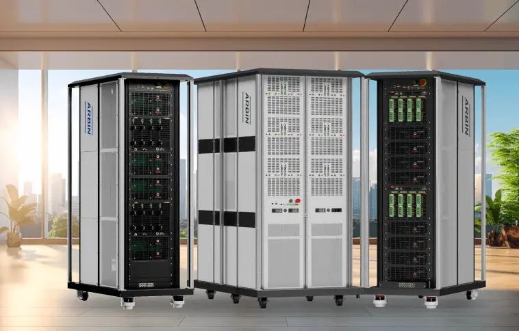
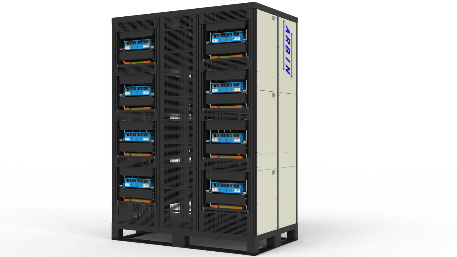
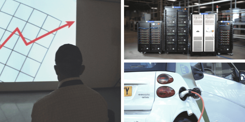
Arbin works with electric vehicle industry leaders around the world, and provides a comprehensive battery test solution for cells, modules, and packs of all sizes.
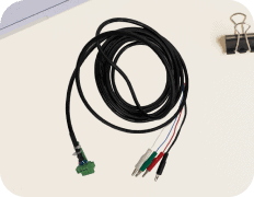
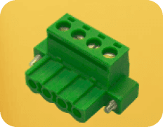
These tests can be easily performed and installed by Arbin’s equipment and accompanying accessories to ensure the accuracy and reliability of the results.

Compared to traditional battery cycling that may use exclusively constant current and constant voltage (CC-CV) charge/discharge profiles, EV testing applications require both cells and battery packs to be charged/discharged based on various real-world applications. These charge/ discharge profiles are highly dynamic and require much greater current demands relative to “traditional” testing.
 | The US Council for Automotive Research, Environmental Protection Agency, and local state governments have all developed and published testing standards for benchmarking batteries and electric vehicle performance. |
Federal Urban Drive Schedule (FUDS) | Hybrid Pulse Power Characterization (HPPC) | Dynamic Stress Test (DST) | Peak Power Test | US06 | FTP EPA75 | HWFET | NYCC | LA92 | and many more.
 | The UN Economic Commission has developed the Worldwide Harmonized Light Vehicles Test Procedures (WLTP) standards for electric vehicle battery testing that is now followed by Europe and most Asian counties (India, Japan, Malaysia, S.Korea, Thailand, Vietnam, etc.) |
I. Hybrid POWER PULSE CHARACTERIZATION (HPPC) TESTING
The Hybrid Pulse Power Characterization (HPPC) Test is intended to determine dynamic power capability over the device’s useable voltage range using a test profile that incorporates both discharge and regen pulses.
The objective of this profile is to demonstrate the discharge pulse and regen pulse power capabilities at various depth of discharge (DOD) values for both the Minimum and Maximum PowerAssist goals (10-s discharge, 10-s regen). The normal test protocol uses constant current (not constant power) at levels derived from the manufacturer’s maximum rated discharge current.
HPPC Introduction:
· [BSF] Battery Size Factor: the minimum number of units (cell/modules/or sub-batteries) of a given design required for a device to meet all targets, including cycle life and calendar life. Wherever possible, the Battery Size Factor will be specified by the manufacturer, based on the manufacturer’s testing and best estimates of any allowances needed for system burdens and degradation over life.
· [Vnominal] Nominal Voltage: Difference between Vmax and Vmin. i.e. Total Energy / Total Capacity
· [IHPPC] HPPC Current = [PCPD] Constant Power Discharge target / (Vnominal * BSF)
· Low Current HPPC Test: Discharge pulse = [IHPPC] * 2.5
· High Current HPPC Test: Discharge pulse = 75% of max current rating, where max current is the manufacturer’s absolute maximum allowable pulse discharge current for 10 seconds
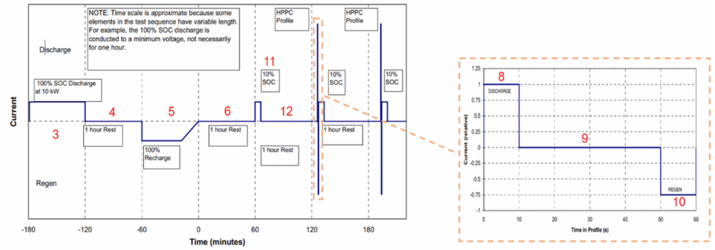
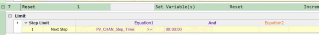
| Time Increment(seconds) | Cumulative Time(seconds) | Relative CurrentsPulse |
| 10 | 10 | 1.00 (discharge) |
| 40 | 50 | 0 |
| 10 | 60 | -0.75 (regen) |
Arbin Battery Cycler Overview of Test Profile
*Note: HPPC Discharge and Regen rate should be defined by the “Low Current HPPC” or “High Current HPPC” rates, or based on manufacturer recommended values.
**Note: Vmin and Vmax should be based on manufacturer recommended values.
***Note: Discharge rate should be based on IHPPC, or manufacturer recommended values.
Method 1: Using constant current control type (The value of currents here are for your example only, it will depends on the battery)
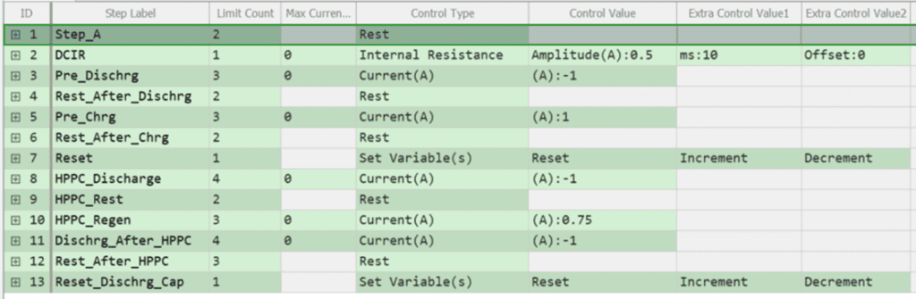
Arbin Step #
Corresponding to each section of HPPC Test.
Battery Cycler Testing Profile
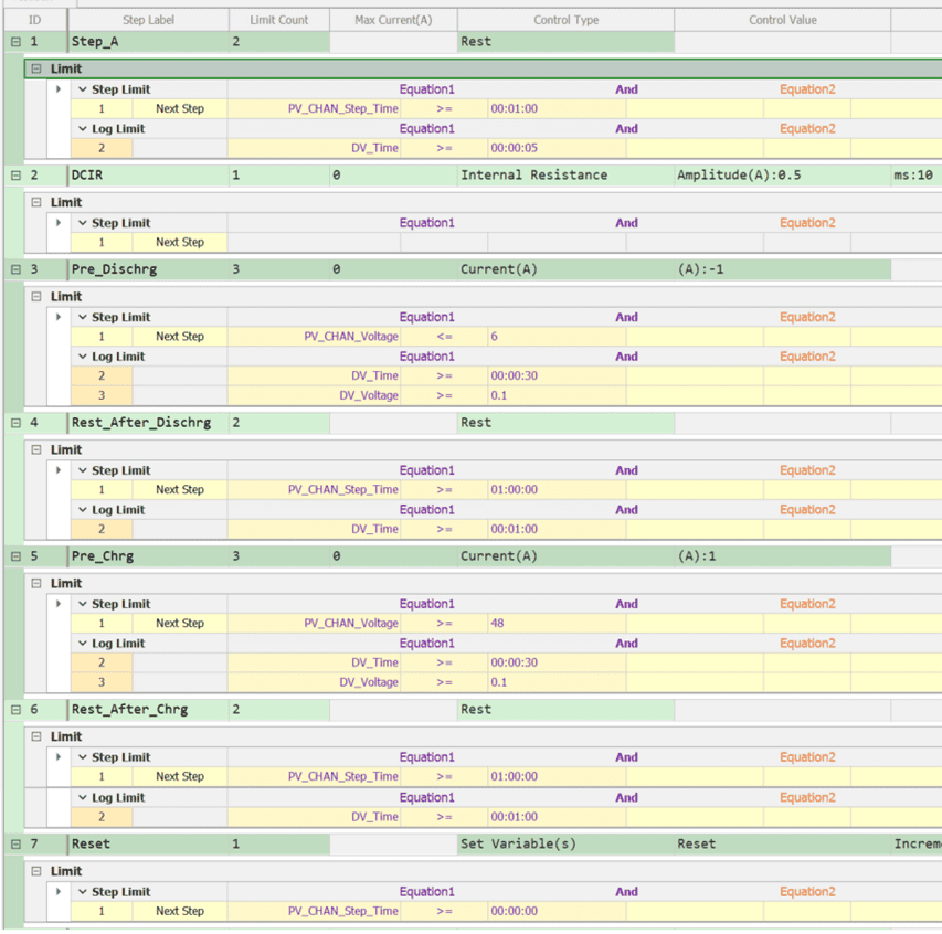
- OCV measurement for 10 seconds
[log every 5 seconds]
- DCIR measurement
- Pre-Discharge* to Vmin**
[log every 30 seconds and every 100mV
change.]
- Rest after discharge for 1 hour
[log every 1 minute]
- Pre-Charge* to Vmax**
[log every 30 seconds and every 100mV
change.]
- Rest after charge for 1 hour
[log every 1 minute]
- Reset Charge & Discharge Capacity and Energy, and TC_Discharge_Capacity1 Counter
Increment Cycle_Index
*Note: Charge and Discharge rate should be based on manufacturer recommended values.
**Note: Vmin and Vmax should be based on manufacturer recommended values.
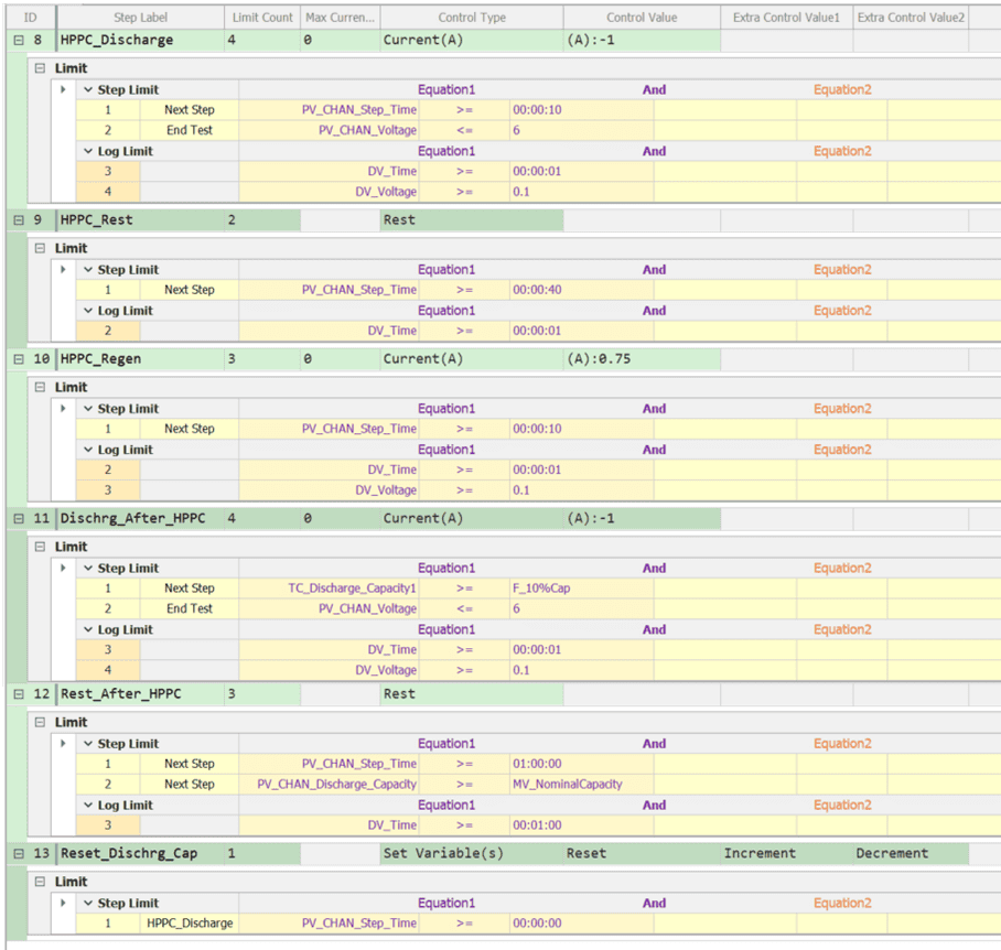
- HPPC Discharge* for 10 seconds.
End test if Vmin** is reached
[log data every 1 second and every 100mV change]
- HPPC_Rest for 40 seconds.
[log data every 1 second]
10. HPPC_Regen* for 10 seconds
[log every 1 seconds and every 100mV
change.]
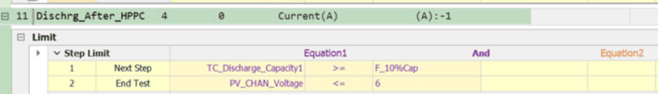
11. Discharge***_after_HPPC until 10% of rated discharge capacity is reached.
End test if Vmin** is reached.
[log every 1 seconds and every 100mV
change.]
12. Rest_after_HPPC for 1 hour.
End test when Discharge Capacity reaches 100% of Nominal Capacity.
[log data every 1 minute]
13. Reset TC_Discharge_Capacity1 and repeat HPPC profile.
Method 2: Using current simulation control type
The method 1 is for better explanation of each step. In reality, for HPPC test, many people using current simulation method, which mean combine all the charge and discharge step into one step of “current simulation”.
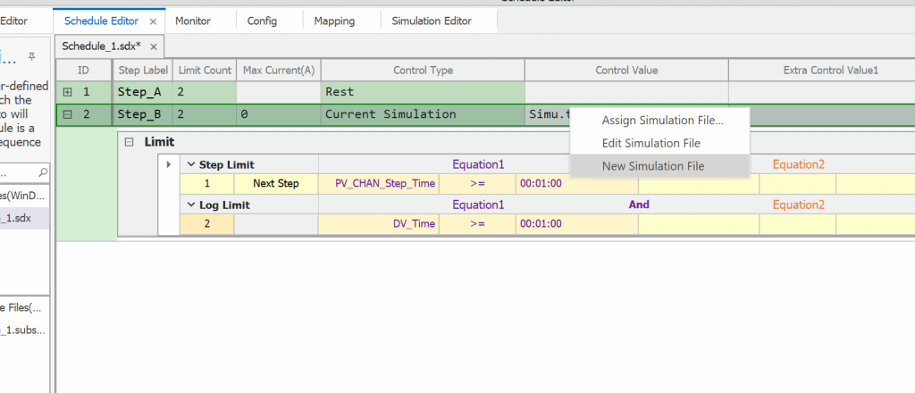
To make this in the schedule, choose control type Current simulation, then choose Control value as Simulation File:
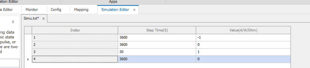
You can set values for this file as follow to replace the step 3 to 6 in the above schedule.
Then the next step will be kept as the step 7 above:
The step from 8-11 can be replaced by this simulation:
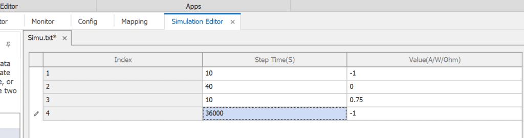
You should apply step limit of step 11 for this second simulation
II. COLD CRANKING TEST
The Cold Cranking Test is intended to measure 2-s power capability at low temperature (normally -30ºC) for comparison with the Cold Cranking Power target(s). The test is conducted at the maximum DOD (minimum state-of-charge) where CS and CD Available Energy targets are just met, i.e., after removal of the energy required by both targets, based on the most recent L-HPPC data.
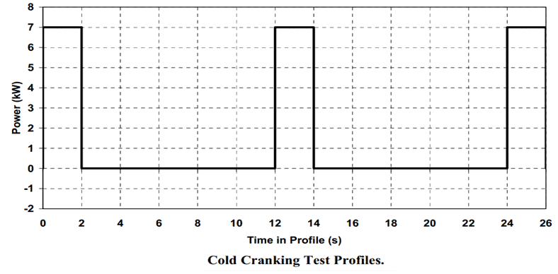
Cold Cranking Test Profile:
The Cold Cranking Test Profile is a literal implementation of the Cold Cranking Power targets, which require the ability to provide 7 kW of discharge power for three 2-s pulses at 12-s intervals (i.e., 10 seconds between pulses). The profile is defined in Table and illustrated in Figure below for the Plug-In Hybrid Battery targets.
| Time Increment(seconds) | Cumulative Time(seconds) | System Power(kW) |
| 2 | 2 | 7 |
| 10 | 12 | 0 |
| 2 | 14 | 7 |
| 10 | 24 | 0 |
| 2 | 26 | 7 |