


Information and Instructions for using the Simulation control types.
1. General Description
Simulation refers to the ability to input data collected from a non-formulated dynamic regime (i.e. other than Constant Current, Constant Voltage, Constant Power, Ramp, Staircase, Pulse, or Formula) as a control function. There are three control types:
1. Current Simulation – uses a current (A) -vs- time (s) profile
2. Load Simulation – uses a Load (Ohm) -vs- time (s) profile
3. Power Simulation – uses a power (W) -vs- time (s) profile
참고:
-
Simulation is generally used on less than 16 channels per channel board. We encourage no more than one simulation profile be run per microcontroller
2. Data Control/Collection Rate
The simulation control interval is suggested to be 10ms or longer for best performance.
Simulation control supports automatic logging data whenever control value changes. User can also set additional logging criteria in log limit.
3. Common Applications
Simulation is very common within the EV market. Many USABC tests such as the FUDS require simulations. The power tool industry is another market that commonly uses simulations.
4. Creating a Simulation Profile
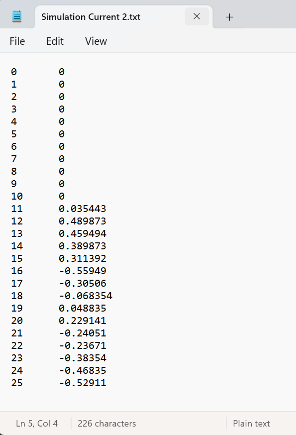
Simulation profiles may be written or copied from any source, but must be saved in a .txt document. Microsoft Windows Notepad is an easy choice.
Data should be entered in two columns for Current, Voltage, and Power profiles.
The left column is time (in seconds) and the right column is the control value (in amps, volts, or watts). Make sure there are no missing values and the number of values in each column is equal. The space between columns does not matter as long as it is consistent.
The user can create a new simulation profile text file from within the MITS Pro software. This will be shown below.
Note: by nature, each line represents a pulse.
-
The pulse amplitude is defined by the right column
-
The pulse ending time (not the starting time) is the value on the left column
-
The pulse starting time is the ending time of the previous pulse (defined in the upper line)
-
The first pulse’s starting time is 0 by default
5. Performing a Simulation – We will create a current-vs-time simulation profile
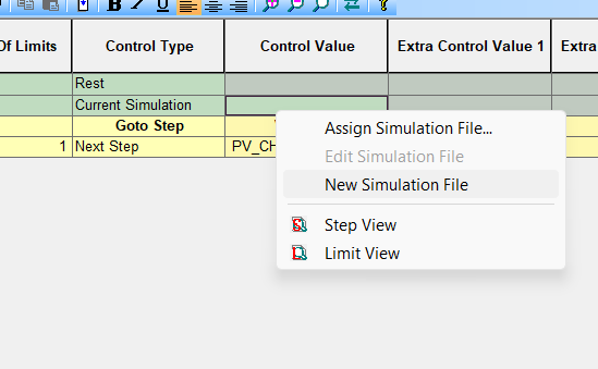
Step 1. The desired control type may be selected from the list as shown. For our example, we will choose a current simulation.
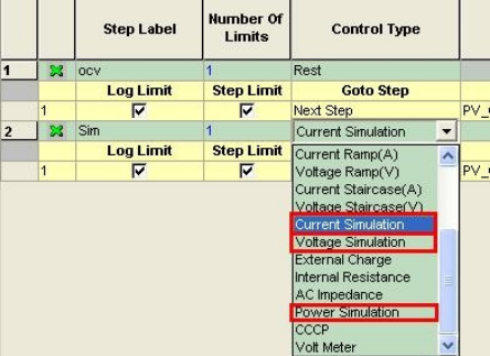
Step 2. Right-click in the Control Value field and you may either Assign a Simulation File or create a New Simulation File.
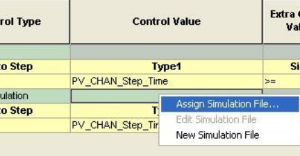
-
Assigning a Simulation File will list all .txt files saved in the Profile Simulation folder if you have already created a simulation profile. C:\ArbinSoftware\MITS_PRO\Profiles_Simulation
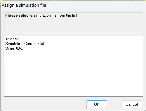
-
Creating a New Simulation File will automatically open a new Notepad .txt file where data can be entered. As stated previously, the left column is time (sec) and the right column is the control value (amps, volts, or watts). The space between columns does not matter.
Below is the finished test schedule to run a current simulation. Note the limit for step duration should be slightly longer than your simulation will run. Data will be logged every 1 second AND with a change in current of greater than 1mA in this example.
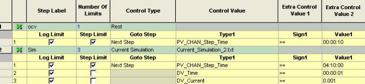
If you want to repeat the simulation profile multiple times (for example, three times), you can choose either “Repeat without extra 2 points” or “Repeat with extra 2 points”, and control the number of cycle by setting the step time limit. For instance, if your simulation profile lasts 500 seconds, you can set the step time limit to 1501 seconds.
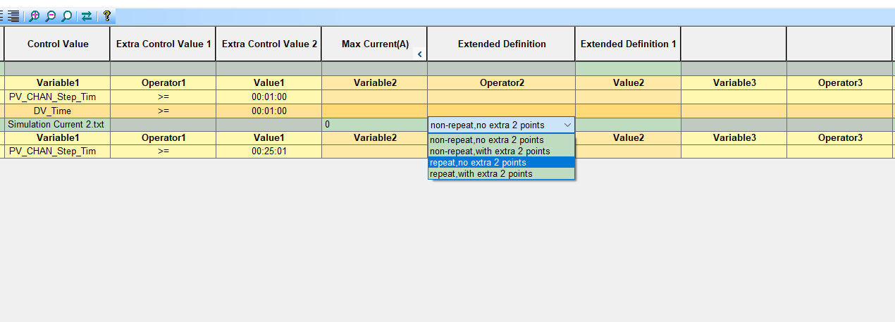
그리고 “extra 2 points” option adds two additional data points—one at the beginning and one at the end—of the logged data set for each line in the simulation file.
참조:
https://www.arbin.com/battery-test-equipment/electric-vehicle-battery-testing.html

